The term “Venturi effect” is not necessarily well-known. However, it features in our everyday lives quite often. Several of our machines like the vacuum cleaner, ventilators or the diffuser in an automobile, are based on this phenomenon.
The Venturi effect is defined as the drop in static pressure of a fluid as it flows subsonically through a constricted area of a pipe.
First, let’s have a look at the mathematical background, and then we’ll see how we can use it.
Basic Fluid Dynamics How Does the Venturi Effect Work?
When a fluid (gas or liquid) in the subsonic regime is forced through a pipe that has a smaller cross-section, the static pressure decreases. The ideal, inviscid, incompressible form of the Bernoulli equation describes the relationship between velocity and pressure:
$$ p_1 – p_2 = \frac{\rho}{2} (v_2^2 – v_1^2) $$
where p is pressure, \(\rho\) is the fluid density and v is velocity.
The above equation shows that, in the event of a pressure drop, the velocity increases and vice versa. This behavior is observed in the case of viscous and weakly compressible flows. However, the change in density and the presence of friction affect the phenomena. If we are familiar with the principle of mass continuity (velocity should increase) and the conservation of mechanical energy (pressure should decrease), the phenomena are straightforward.
But why are we investigating only subsonic flow? The question leads us to the consideration of the sound-speed barrier, where the presence of the shockwave prevents any further increase in volume flow rate via the increase of the upstream pressure. By mounting a divergent nozzle downstream in the system, we can create the de Laval nozzle, which is the supersonic “version” of the Venturi effect.
Download our ‘Tips for Architecture, Engineering & Construction (AEC)’ white paper to learn how to optimize your designs!

Venturi Effect Everyday Cases and How to Benefit From Them
Garden Hose
One example that almost everybody has experienced is when the thumb is placed at the end of a garden hose. The water’s velocity increases when you place your thumb over the water, introducing a decrease in the hose cross-section. The pressure increases over the smaller surface area, while the narrow flow then creates a vacuum in the water. The fluid’s kinetic energy increases resulting in a pressure decrease.
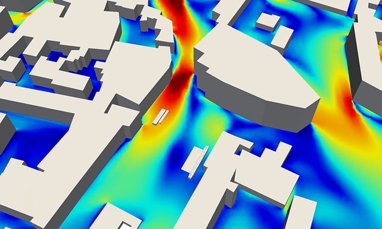
Wind in Urban Areas
Another effect, but one that is less comfortable, is when the wind enters a narrow section in a built environment. The airflow in this space experiences a pressure drop and, on the other side, as we already know, the velocity of it rises. This explains regions in cities that are significantly windier for occupants than others. A wind experiment carried out in an urban area will often reveal the Venturi Effect as well as many other useful revelations. You can find more information on wind experiments here.
Fuel Injectors and Jet Pumps
Although jet pumps or fuel injectors are based on the so-called ejector mechanism, they also benefit from the Venturi effect. As the fluid with the higher speed enters the smaller cross-section, it creates a vacuum and gives momentum to the other fluid.
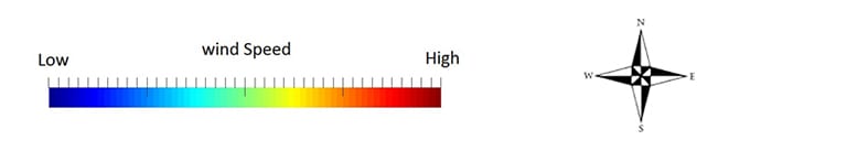
Venturi Meter or Venturi Tube
By measuring the change in pressure, the flow rate can be determined by using a Venturi tube. The device is used in several industrial applications because it is the simplest and most accurate form of volume flow rate measurement. Manometers or transducers are installed on the two different sections (“free flow” and small”) to measure the pressure difference, as shown in the picture above. Since we know the geometry of the Venturi meter (A1, A2), and the fluid itself (viscosity and density), the flow rate can be easily calculated via:

where Q is the volumetric flow rate, A is the cross-section, and the other symbols were discussed before already. Since the geometry does not change, we can conclude the following:
- the higher the pressure difference (the lower p2), the higher the flow rate
- the flow rate can be increased by decreasing the fluid density
Orifice Plate
A similar application to the Venturi tube is the orifice plate, which uses the same relationship between pressure and velocity for flow rate measurement.
The difference is that the device consists of a thin plate with a hole in it, increasing the pressure upstream and accelerating the flow in the hole and downstream. In order to calculate the mass flow rate, the orifice plate has to be calibrated so that the coefficient of discharge is available. More information on calibration, the expansibility factor, and ISO regulations can be found in this Wikipedia article.
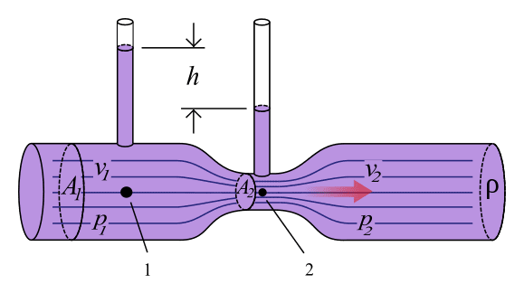
Basic Carburetor
Older cars and even some recent motorbikes are using a carburetor to prepare the fuel-air mixture for the engine. This part of the vehicle consists of an open pipe through which the air passes to the intake manifold. It has the form of a Venturi tube (see above), where the pressure drops in the smaller cross-section, exactly where the fuel nozzle is installed. The airflow can be controlled with a throttle valve so that a proportional amount of fuel will always be injected into the flow.

Explore CFD in SimScale
Aquarium Aerators
Filters in the hobby and large aquariums are also using the Venturi effect for aeration. A small pipe connected to the ambient air is mounted on the underwater outlet pipe of the filter. The Venturi effect of the flow there causes a pressure depression, resulting in the air being sucked into the filtered water flow.
To learn about other effects in building design and applications of CFD simulation in the construction industry, read this blog article: Assessing Wind Comfort in Urban Areas with CFD.
In addition, you can watch the recording of the webinar “Pedestrian Wind Comfort Assessment with Cloud-Based CFD”. Just fill out this short form and the webinar will play automatically.


