Elastomers are increasingly used in industrial applications, so understanding their mechanical behavior is more important than ever before. Tires are one of the largest application of rubber material, with some other very common industrial applications including seals, bearings, dampeners, O-rings, etc.
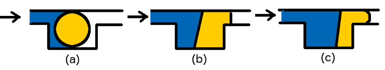
O-rings were invented in the 1890s and are used to seal fluids. O-rings are present in almost all industrial and commercial applications and work on the concept of balancing the fluid pressure with the contact stresses. As the fluid pressure increases, the O-ring is compressed in the direction normal to the fluid surface. This is demonstrated in Figure 1. As elastomers are incompressible, they will expand in the transverse direction to increase the contact stresses and effectively seal the interface. The sealing does not fail as long as there is no mechanical failure of the O-ring, which is one of the primary reasons they are still widely used.
In this article, we discuss a series of tips for modeling elastomeric materials using the finite element method (FEM) to improve the accuracy and reliability of obtained solutions.
Choosing the Right Material Model for the Elastomers
Elastomeric and rubber material typically demonstrates:
- Isotropic and elastic behavior without any permanent set (like plasticity)
- Nonlinear stress-strain behavior, as shown in Figure 2.
- Different tensile and compressive behavior and is comparatively softer in tension
- Nearly incompressible behavior with a Poisson ratio of around 0.4999

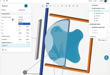
While most of these characteristics are captured well through hyperelastic models, a suitable model should always be selected based on the material behavior. The material parameters are obtained through experiments like uniaxial and biaxial tensile test, uniaxial compression test, planar, simple shear, and volumetric test. A more detailed discussion on the selection of hyperelastic material model can be found on the SimScale blog.
Tip 01: Using the parameters highlighted in this blog article, choosing the right hyperelastic material model is half the job done well.
The purpose of a helmet is to protect the person who wears it from a head injury during impact. In this project, the impact of a human skull with and without a helmet was simulated with a nonlinear dynamic analysis. Download this case study for free.

Meshing the Structure
At present, SimScale allows for the meshing of the structures with tetrahedrons. Hence, in this article, we will limit the discussion specifically to meshing 3D structures with tetrahedrons. A general overview of meshing and a complete meshing tutorial are available in the SimScale documentation. SimScale currently allows tetrahedral meshing with following options:
- Automatic
- Parametric
- Tetrahedral with local refinement
As shown in Figure 3, all of these cases allow for the specification of mesh order: first or second. Using a first-order mesh generates a mesh with four-noded tetrahedral elements and a second-order mesh creates one with ten-noded tetrahedral elements. For more detailed tips on meshing for structural mechanics problems, watch out for our upcoming articles.
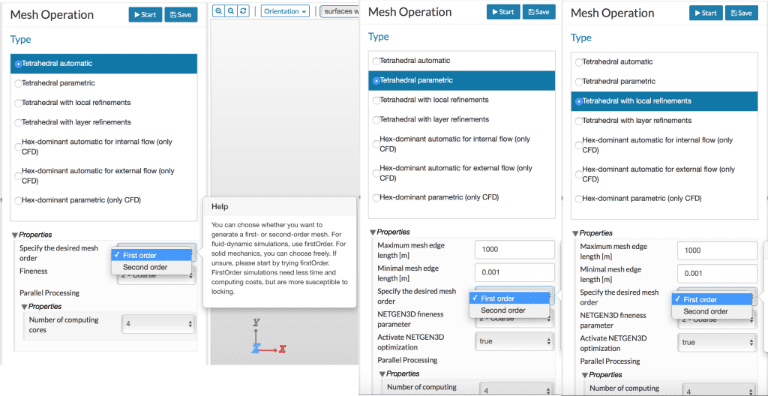
Tip 02: For most elastomeric structures, a second-order mesh would be the safest choice. However, in some cases, a first-order mesh could also be sufficient and save significant computational time.
Considering Geometry and Loading
A key factor that plays a role in the accuracy of the solutions is the dimensions of the applications of elastomers—like conveyor belts, for example—have one or more dimensions (like length and breadth) that are much larger than the others (thickness).
This is demonstrated further in Figure 4, where the thickness and breadth of the structure are much larger than its length, and it can be considered as a beam. Similarly, if the thickness is much smaller than both the length and breadth, then the structure can be considered as a plate or shell. If all the dimensions are comparable, then the structure can be considered to be a full solid. Irrespective of the structure type, solid elements are always used to mesh the structure. Thus, it becomes important to understand the form of a structure so that effective meshes can be generated.
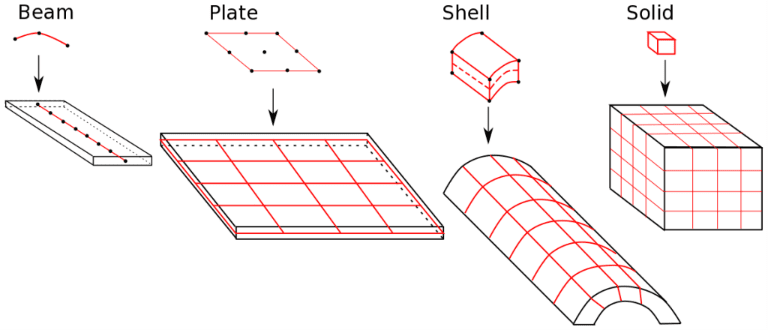
It is important to first identify the category of the structure. For solid structures, the automatic tetrahedral meshing can be directly used, and the first- and second-order meshes could both yield good results. However, the complexity increases significantly when we consider structures that resemble beams, plates, or shells.
Secondly, in addition to geometry, it is also important to identify the type of loading these structures are frequently subjected to. For example, the O-ring illustration demonstrates that the loading on the elastomer structure is of bending-type in nature.
When the structures are of the form of beams, plates, or shells, they can be classed as thin structures. These thin structures demonstrate a locking effect (commonly known as shear locking) especially when a first-order mesh is used and the structure is subjected to bending loads. The easiest way to circumvent the shear locking is through mesh refinement or using higher-order elements. For a more detailed discussion on the shear locking, watch out for our upcoming blog article on meshing tips for structural mechanics problems.
Tip 03: If you are using a solid structure, a first-order mesh might still work. If the structure can be classified as one of the thin structures and/or subjected to bending loads, then a second-order mesh is strongly recommended.
Dealing with Incompressibility in Elastomers
Most elastomers and rubbers have a Poisson ratio of almost 0.5. Physically, this means that when the material undergoes elongation in the x-direction, there is enough compression in the other two directions to retain the same initial and final volumes. Note that a Poisson ratio of 0.5 is equivalent to saying that the bulk modulus is infinity.

Otherwise, this means that it would take an infinite amount of energy to compress the material. To get a more realistic feel for the idea, one could consider water. Water is a perfect example of an incompressible material. If you fill a can with water and try to compress it, it is obvious that the volume of water remains unchanged. It might burst or spill from the can, but the volume of water does not change. So one could say that the bulk modulus of water is almost infinity. Since infinity cannot be used numerically, a very large bulk modulus is used to signify a Poisson ratio that tends to 0.5.
When the bulk modulus is considered, and the Poisson ratio is larger than 0.4, most normal elements display a locking effect. This is commonly known as volumetric locking. Unlike the earlier discussed shear locking, volumetric locking cannot be circumvented through mesh refinement. Volumetric locking is not only common to elastomers but also pertinent to any elastoplastic material.
There are several approaches available in the literature:
- Selectively reduced integration (B-Bar method)
- Uniformly reduced integration (or more commonly known as reduced integration)
- Enhanced strain formulation
- Mixed formulations
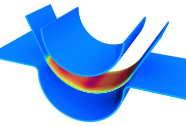
First, before seeking a solution, it is important to understand the cause of this volumetric locking. Let’s consider a simple example of a loaded structure made of elastomer in 2D, as shown in Figure 6, where the cause of volumetric deformation is observed. The mesh is made of two triangles—alternatively, it could be one quadrilateral with linear interpolation (first-order mesh). A small force—or displacement—is applied to the free node (node number 01) along the direction of 45-deg.
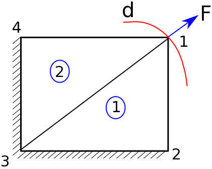
Since the material is volume preserving and the elements use linear interpolation (i.e. lines 1-2 and 1-4 need to be straight), the free node can only move along the circle shown in red. However, this would mean moving perpendicular to the effective reaction force, and such a motion cannot be allowed. Eventually, the only possible solution is the trivial solution of nodal displacements being zero—or small numerically insignificant. This is clearly disastrous!
One of the simplest ways to solve the problem is using second (or higher) order elements. When second-order elements are used, the edges do not need to be straight anymore. This would facilitate motions that could lead to non-zero nodal displacements and still conserve the volume. However, as the Poisson ratio approaches 0.499, 0.4995, etc., even the second-order elements do not behave well. To understand this behavior of second-order elements, it is important to understand the mathematics behind the interface.
In problems involving elastomers and rubber material (or nonlinear FEM), matrix equations [K]{u} – {f} = {R} are solved such that {R} tends to zero. The stiffness matrix [K] is first computed locally for each element and then assembled to a bigger global system. Locally, in each element, [K] is computed at fictitious points, commonly known as Gauss (or integration) points. The above problem with second-order elements is a result of the volumetric strain that is being forced to remain at zero at all of these integration points. The total energy from volumetric strain can be approximately written as a product of the bulk modulus x (volumetric strain)^2. Since the bulk modulus is very large, even a small volumetric strain can lead to a significant addition to the energy. This renders the total equation system to behave very stiffly, and the solvers converge more frequently to the trivial solution (one of zero displacements).
A commonly used alternative, one which is also incorporated in SimScale, is using reduced integration with second-order elements. This means that the deviatoric strains are computed as earlier, but the zero volumetric strain is enforced only at certain points. While this might sound inaccurate, the reduced integration has been observed to be extremely robust and has proven to yield quite accurate solutions across a wide range of Poisson ratio.
Note that first-order tetrahedrons use only one integration point and thus a reduced integration with these elements is not possible.
Tip 04: If the Poisson ratio is less than or equal to 0.4, first-order elements can be used. For Poisson ratios up to 0.45, second-order tetrahedrons could work well. For much higher Poisson ratios, it is strongly recommended to use second-order elements with reduced integration.
Force vs. Displacement Boundary Condition for Modeling Elastomers
One of the most common causes of non-convergence is unbalanced residuals. When modeling elastomers, the system of equation being solved is nonlinear, i.e. [K(u)] {u} – {f} = {R}. Here the stiffness matrix [K(u)] is a function of the unknowns {u}. Thus, small displacements or forces are applied in minor increments to reach the desired value.
Using smaller time steps (i.e. smaller force increments) can significantly improve the convergence properties. Alternatively, if possible, displacement controlled boundary conditions are most likely a safe option. As shown in Figure 5, where a very highly nonlinear problem is considered, for every displacement, there is a unique solution for the force. However, the same is not true in reverse.
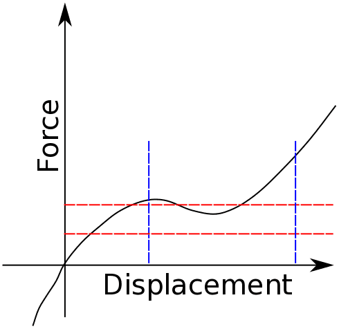
This means that when a force boundary condition is applied, it need not lead to a unique displacement. Such non-uniqueness can easily lead to a lack of convergence. Alternatively, using a displacement boundary condition can lead to a better convergence. In such cases, advanced techniques—such as line search, among others—are employed to improve the overall convergence of the system. Watch out our SimScale blog for the upcoming article related to solvers for structural mechanics problems that will delve deeper into areas like line search, etc.
Tip 05: If possible, use displacement boundary conditions.
Convergence Issues
There are several reasons why a simulation can fail and show a lack of convergence. Some of the very common ones pertaining to elastomers and rubber material include, but are not limited to:
- Material instability
- Time step size
- Inelastic effects
Material instability
The material parameters are generally obtained by fitting the experimental data. The fitting is limited by the maximum stretch to which the data is available. If the model is used beyond this limit, the model might not be unconditionally stable.
For example, let’s consider a scenario where the data was only available for a stretch to 30% and the model parameters were fitted with this. When a simulation is done using this model, where the strains are much larger (> 30%), it is possible that the nonlinear behavior beyond 30% is not accurately captured.
Secondly, depending on the number of tests used for fitting, it is possible that the material demonstrates an instability when subjected to a different type of loading. For example, if the material parameters for the Mooney-Rivlin model are fitted using only uniaxial tests, then when a biaxial simulation is done, it is possible that the results show significant instabilities.
A possible solution to this would be to test the material model with uniaxial, biaxial, shear, volumetric tests for up to failure limits. Using these simulations, possible points of material instabilities can be identified a priori.
Time-step size
The second possible reason for the lack of convergence can be time-step size. If a manual time step is used and if the time step is too large, it can result in a lack of convergence. SimScale allows for auto time-stepping and it is recommended to use this auto-stepping.
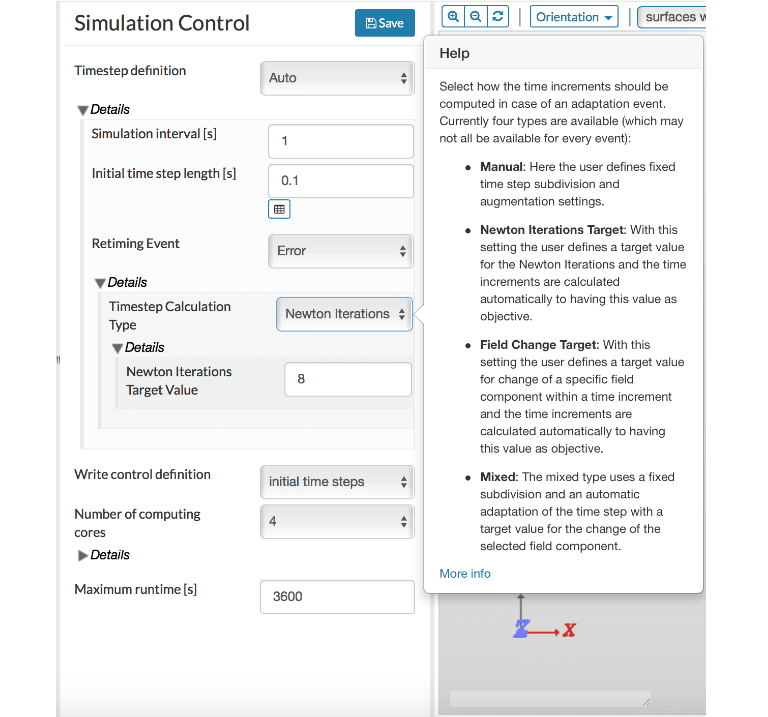
As shown in Figure 8, a retiming event is used to reduce the time step. When the time step is too large and leads to non-convergence, this triggers a retiming event. In these instances, the time step is reduced, and the simulation restarts from the last converged time step. This significantly reduces the failure of simulations. There are several options available for time-step calculation type, and the “Newton Iterations Target” option is a good place to start.
Inelastic effect
In this article, we have considered the elastomers to be purely hyperelastic, and we will discuss the effects of inelasticity in an upcoming blog article
Tip 06: Check the material parameters thoroughly for instability before using it under general loading conditions. Auto time-stepping is a great way to prevent failure of simulations!
Overall, summarizing the type of problem or procedure, types of element recommended or suggested to avoid are:
- Bending and thin structures: second-order (recommended), first-order (avoid)
- Nearly incompressible (Poisson ratio > 0.45): second-order with reduced integration (recommended), second-order with fully integrated (avoid)
- Very large deformation: second-order (recommended), first-order (avoid)
- Boundary condition: displacement (recommended), force (avoid)
- Time-stepping: auto (recommended), manual (avoid)
Discover all the simulation features provided by SimScale. Download the document below.