Pipeline flexibility analysis is one of the most common applications of structural engineering. Pipes are used for transporting many products, from oil and its derivatives to water and even solids and powders, at varied temperatures and pressure levels, under an infinite number of possible geometric configurations. For this reason, each individual pipeline is subject to a particular stress condition, which needs to be evaluated to ensure safety.
Many types of loads impose structural stress over a pipeline, for example:
- Gravitational Loads: weight of the pipe, weight of accessories such as valves, weight of the product
- Pressure Loads: internal pressure, vacuum
- Thermal Loads: stress due to thermal expansion/contraction
- Other loads: wind, earthquakes, differential ground settlement.
In situations such as these, it is the responsibility of the stress engineer to ensure that the pipeline is safe to operate. Local and international engineering codes impose guidelines regulating the loads and allowable stress values in the pipes, but generally, they don’t impose an analysis methodology. Many different analytical and numerical methods exist, such as comparing the design to a similar, proven safe pipeline, but engineering simulation (computer-aided engineering) has now become the industry standard.
In this context, finite element analysis (FEA) is employed mainly to analyze stress concentration and localized stresses in a pipeline—for example in tee-junctions or support locations, for more advanced studies like fatigue and fitness for service. But there are many advantages in using FEA for the more common calculations as well: we can, for example, apply many loads at the same time, use realistic thermal deformations models that take into account local geometry, analyze heat transfer, apply pressures, and even go further and take into account non-linear phenomena such as friction in supports and plasticity. And with the advantages of cloud-based simulation, we don’t have to worry about the problem size and computing power, hardware management or software licenses.
Pipeline Flexibility Analysis: Practical Example
Problem Definition
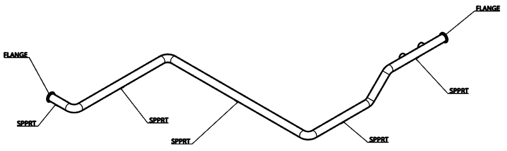
In the problem we are going to tackle, we have a 42 m, 24-inch standard schedule pipeline run, which carries heated crude oil from a reservoir tank to a pump. Below is an isometric view:
We considered a typical piping code load case, chosen according to our aim of assessing safety against thermal load, with the following loads:
- Pipe weight
- Oil weight
- Temperature delta of +50 degK on all the pipe (maximum temperature)
- Internal pressure of 700 kPa
Modeling and Simulation
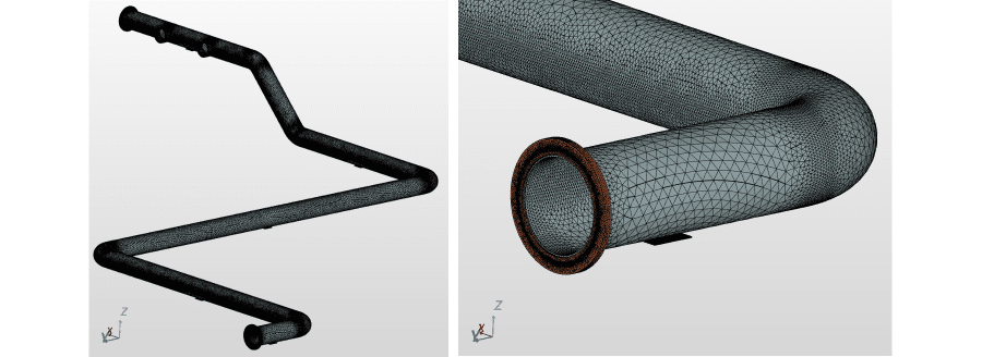
The system was modeled as a solid body and meshed with linear tetrahedral elements. The resulting mesh has the following stats:
- 217658 nodes
- 750794 linear tetrahedral elements
- 8 separate bodies
The following techniques were used to model the load and support conditions:
- To simulate the support conditions, a dummy plate was modeled and linear sliding contact conditions were specified between the upper face of the plate and a matching face close in the pipe (see Figure 2)
- The flanges were connected using bonded contacts
- Fixed boundary conditions were applied to the flange bolt holes and lower faces of the dummy support plates
- Pressure load applied at internal pipe faces
- Oil weight applied as distributed force at internal pipe faces
- Temperature applied uniformly to all bodies
- Weight of bodies as gravity load
Simulation Results
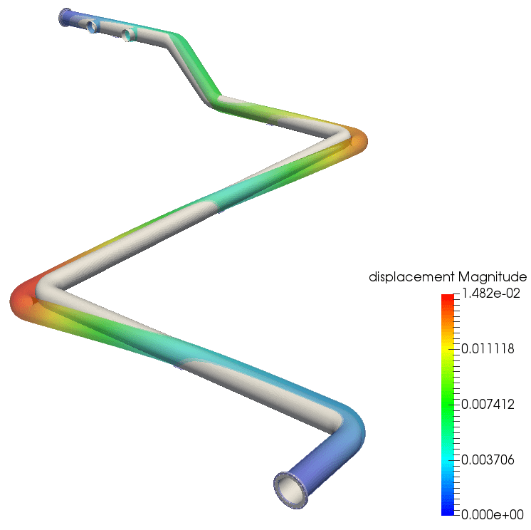
The simulation took 19 minutes to run. Examining the results, the deformation plot shows good flexibility in the system (Figure 3).
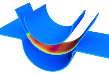
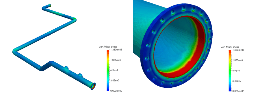
Next, we look at the von Mises stress plot, with the range clipped at the allowable stress. We find red zones (stress higher than allowable) at the flanges joints (Figure 4).
We find that the stress condition is acceptable throughout the whole pipeline, except for the section of the flange joint. This stress concentration could be due to a number of possible reasons, such as the numerical effects, the bonded contacts we are using for the joint, the boundary conditions, or lack of refinement.
Stress concentration could be a real physical effect (as opposed to numerical errors), so engineering judgment must be used to accept or reject the stress condition. Consider that the flange is a more substantial body than the pipe, so thermal expansion is higher and therefore may create a blockage, which also exerts pressure because of the internal face expansion. Considering the reported maximum stress of 184 Mpa, yielding could occur on this small portion of the pipe, leading to stress redistribution. It remains to be seen if failure is to be expected.
Further simulations could also be carried out to investigate this effect, like a local, fully refined analysis, transposing deformations from the global analysis as load condition. A nonlinear simulation for plasticity stress redistribution could also be carried out. But for now, we will take these results as they are.
SimScale’s CEO David Heiny tests the capabilities of the platform to solve a real-life engineering problem. Fill in the form and watch this free webinar to learn more!

Conclusion
Piping design is essential in a wide range of industries, from oil and gas extraction and transportation, refineries and power stations, to HVAC and cooling systems in engines and turbines. In this article, I have demonstrated how to leverage the power of FEA and cloud simulation through the SimScale platform for a pipe stress analysis. I carried out a detailed simulation (0.65M Dof) with solid elements and contacts at the supports to investigate the stress conditions arising from a typical piping code load case. The project we used can be found in the SimScale Public Project Library, which has a variety of freely available piping design analyses examples, including:
- Thermostructural Analysis of a Cracked Pipe
- Scalar Transport in T-Junction Pipe
- Bending Analysis of an Aluminium Pipe
- Comparison of Pipe Junction Designs
Simulation offers advanced tools to analyze and tackle these and many other engineering problems involving stress and fluid flow behavior analysis in pipe networks. To test it yourself, create a free SimScale account here and leverage the platform’s FEA, CFD, and Thermal Analysis features to optimize and validate your own designs.