With the surge of climate change and the global push to become more energy efficient in all aspects of life including building ventilation, thermal comfort has become a hotly (pun intended) debated issue in recent years. The purpose of the ASHRAE 55 standard (published by the American Society of Heating, Refrigerating, and Air-Conditioning Engineers) is to specify the various combinations of indoor thermal environmental factors as well as personal factors that will produce thermal environmental conditions acceptable to a majority of the occupants within a space.
ASHRAE 55 defines thermal comfort as “that condition of mind that expresses satisfaction with the thermal environment”, and is used primarily in the United States but is well known around the world as the standard for designing, commissioning, and testing indoor spaces and systems written in parallel with other well known international standards such as ISO 7730. In the following article, we will explain the standard, the parameters, and the model that are used to predict thermal comfort, as well as how SimScale can help engineers ensure compliance with thermal comfort regulations and prevent local discomfort using online CFD simulation.
Thermal Comfort: The History of ASHRAE 55
The ASHRAE standard 55 was first published in 1966 and is updated every 3-7 years based on current research, practical experience, and recommendations from designers, manufacturers, and end users. The most notable, as well as most recent iterations of the standard, are the 2004, 2010, and 2017 updated versions.
ASHRAE Standard 55 – 2004
The 2004 ASHRAE update introduced a few critical changes that lessened the criteria gap between it and its ISO standard counterparts. This included the adoption of the computer model method, the introduction of the adaptive method (or model that relates indoor design temperature ranges to outdoor meteorological parameters) based on research that supports natural ventilation designs, and the recognition of elevated airspeed preference for general occupant thermal comfort.
ASHRAE Standard 55 – 2010
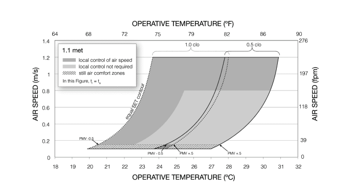
The 2010 update reintroduced standard effect temperature (SET) as the method of evaluating and determining the cooling effect of elevated airspeeds and indoor air movement as a whole, made large revisions to clearly specify mandatory minimum requirements in both design analysis and documentation to comply with the standard, and added a general satisfaction survey and post-occupancy evaluation (POE) as a method of preemptively as well as retroactively evaluating thermal comfort for occupants in a space.
ASHRAE Standard 55 – 2017
The newest 2017 ASHRAE 55 standard update includes a new element that can take into consideration the change in occupants’ thermal comfort from direct solar radiation, in addition to the existing scope, requirements, conditions, and parameters we will discuss below.
The Scope of ASHRAE 55
The standard was primarily designed for thermal comfort in spaces where occupants are in sedentary states (i.e., office work). However, it can also be employed to cover other types of indoor environments, excluding extreme conditions that can be found in ISO 7243, ISO 7933, and ISO/TR 11079. This standard is based upon four pillars:
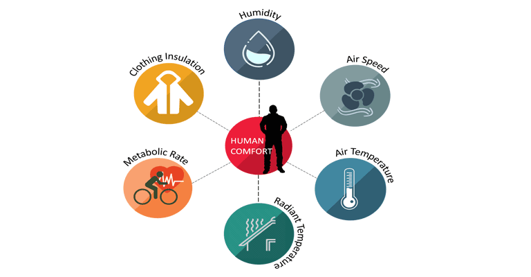
- The six environmental and personal factors taken into account are temperature, thermal radiation, humidity, airspeed, activity level (metabolic rate), and occupant clothing (degree of insulation).
- In order to comply with ASHRAE 55, all of these factors must be accounted for in combination.
- The thermal conditions that ASHRAE aims to achieve are applicable to healthy adult occupants, up to an altitude of 3K meters, where occupancy time must surpass 15 minutes.
- This standard does not take into consideration factors including air quality, acoustics, illumination, or contamination (EN 15251 covers a broader scope of external factors as well as EN 15193, EN 12464-1).
While these factors can vary over time, the framework defined in ASHRAE 55 is only concerned with steady-state cases, where the different parameters and quantity values do not change over time. For evaluating thermal comfort over a period of time, ISO 7730 Section 9 can be referred to.
Important ASHRAE 55 Terminology for Understanding Thermal Comfort
Environmental Factors/Inputs
Airspeed:
The rate of air movement at a given point in time regardless of the direction.
Clo:
The unit used to represent the thermal insulation from clothing, where 1 clo = winter clothing and 0.5 clo = summer clothing. There is a difference between clothing insulation (Icl), which includes even parts of the occupants’ body uncovered by clothing, and garment insulation (Iclu), which only refers to heat transfer obtained from skin-to-clothing contact.
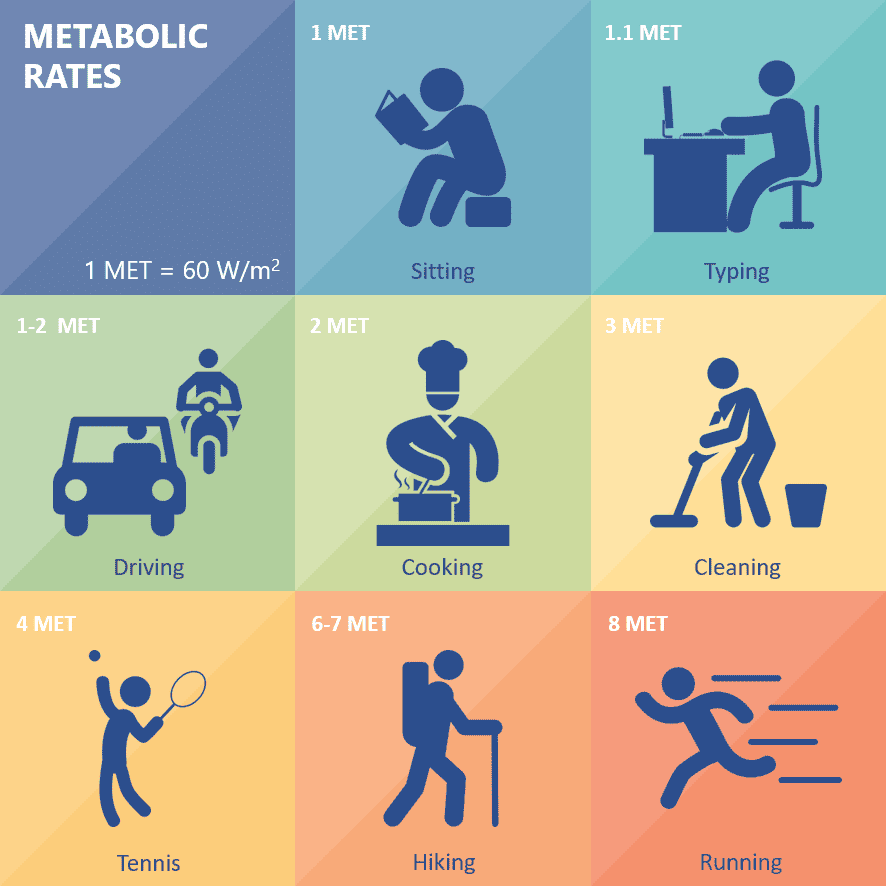
Metabolic Rate (M):
The rate of transformation of chemical energy into heat and mechanical work by metabolic activities within an organism is usually expressed in terms of the unit area of the total body surface. In this standard, the metabolic rate is expressed in met units. This unit is accounted for as the personal activity of occupants, where 1 met is a person at rest.
Relative Humidity (RH):
The ratio of the partial pressure (or density) of the water vapor in the air to the saturation pressure (or density) of water vapor at the same temperature and the same total pressure.
Mean Radiant Temperature (tr):
The uniform surface temperature of an enclosure where an occupant would exchange the same amount of heat as in the actual non-uniform space, calculated from the weighted temperature average of each surface divided by the total area of the space.
Predictive Results/Outputs
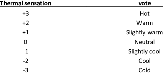
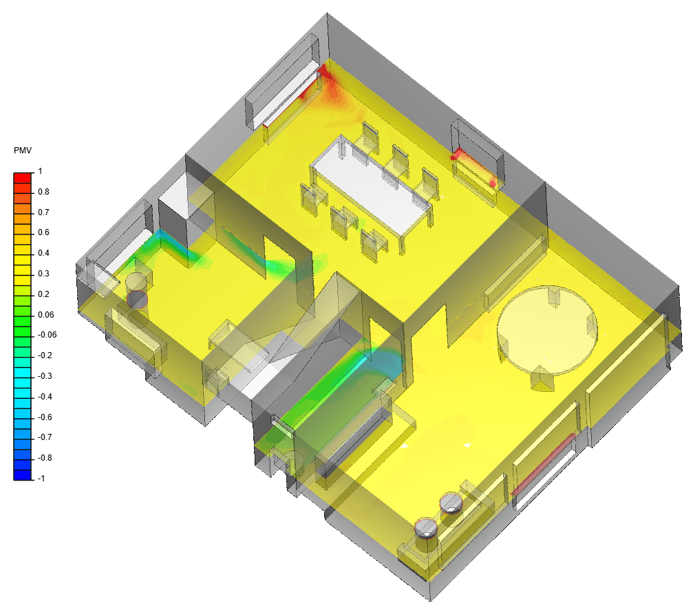
Predicted Mean Vote (PMV):
An index that predicts the mean value of votes of a group of occupants on a seven-point thermal sensation scale that is based on the balance of heat within the human body. This balance, much like thermal neutrality, is obtained when an occupant’s internal heat production is the same as its heat loss. As humans, our thermoregulatory system modifies our temperature by sweat secretions to keep us thermally balanced and to avoid local discomfort. Different methods can be used to assess this for different combinations of metabolic rate, insulation, temperature, airspeed, mean radiant temperature, and relative humidity, and our computation method will be addressed in the latter part of this article.
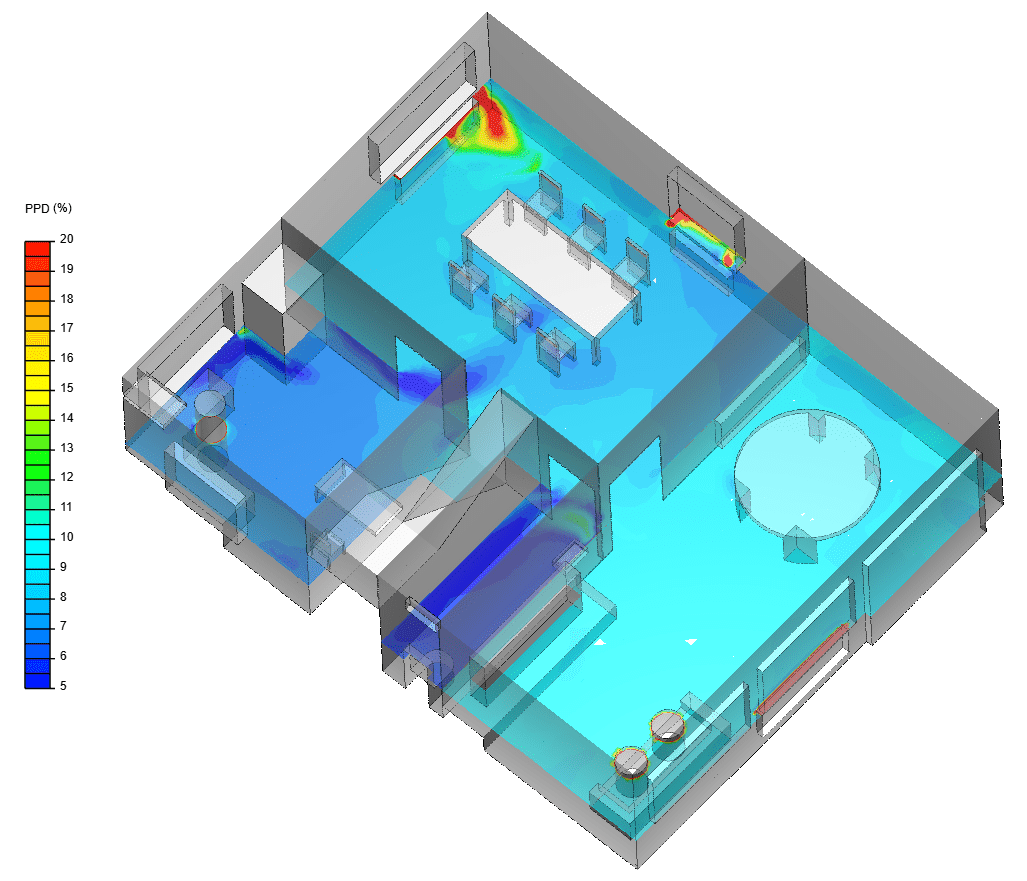
Predicted Percentage of Dissatisfied (PPD):
An index that establishes a quantitative prediction of the percentage of thermally dissatisfied occupants (i.e., too warm or too cold). The PPD is calculated from the PMV, as it can be found from the distribution of individual thermal sensation votes compiled collectively.

Additional Thermal Comfort Terminology to Note
Thermal Neutrality:
The indoor thermal index value corresponding with a PMV vote of neutral on the thermal sensation scale pictured above.
Local Discomfort:
The term for unwanted cooling or heating on a particular part of an occupant’s body. Main causations can include draft, abnormally high vertical temperature differences between the head and ankles, too warm or too cold flooring, or too high of a radiant temperature asymmetry (i.e., a discomfort effect appearing due to a gradient in temperature acting on an occupant. For example, if the right-side wall is at 343K, and the left-side one is at 273K, this gradient will be sensed as discomfort, even if the temperatures are not intolerable.)
Thermal Comfort Basics: ASHRAE 55 Parameters
Indoor thermal comfort can be predicted based on the aforementioned parameters in combination, including air temperature, thermal radiation, humidity, and airspeed, as well as personal factors such as physical activity and the degree of clothing insulation. Numerical methods emerged as a standard tool for the prediction of comfort levels which depend on the previously mentioned environment and personal conditions at an early stage during the design process.
Based on these inputs, SimScale provides thermal comfort parameter outputs based on empirical models in the form of the predicted mean vote (PMV) and predicted percentage of dissatisfied (PPD) fields as developed by P.O. Fanger, following the static model for thermal comfort. To learn more, refer to our SimScale Thermal Comfort Parameters documentation.
General Requirements and Standard Conditions of ASHRAE 55
Sections 4 and 5 of ASHRAE 55 define the requirements and conditions that must be met in order to comply with the standard. General requirements dictate that the standard must be applied to the particular space being considered, the occupants that will be inhabiting the space, locations within that space if not the entire space, as well as any outlier occupants (i.e., children, disabled persons, elderly persons, etc.).
The mandatory conditions that must be met to comply with ASHRAE standard 55 exist in a range of values, as satisfying everyone in a given space is impossible due to unknown variations (physiologically and psychologically). Therefore, ASHRAE 55 recommends a specific percentage of occupants that constitute acceptability and values of the thermal environment associated with this percentage.
Compliance With ASHRAE Standard 55
The comfort zone is considered to be sufficiently comfortable if at least 80% of its occupants can be expected to not object to the ambient condition, meaning that the majority are between -0.5 and 0.5 on the PMV scale. In order for building systems to comply with ASHRAE, including natural ventilation systems, mechanical ventilation systems, combinations of these systems, control systems, thermal envelopes, and so on, design conditions must maintain the spatial conditions within the acceptable range using one of the methodologies outlined in section 5 of the standard. Moreover, they must account for all expected conditions (i.e., summer and winter but excluding extreme conditions), including external and internal environmental factors, and include all necessary documentation.
Needed Thermal Comfort Compliance Documentation
The documentation needed to comply with ASHRAE must consist of all of the following, except in the case of naturally ventilated spaces:
- The design operative temperature, humidity, and total indoor loads.
- The hours of each seasonal exceedance associated with the outdoor weather percent design conditions.
- The values assumed for comfort parameters (clothing insulation, metabolic rate, indoor airspeed, etc.) at the different assumed conditions (i.e., seasonal).
- Local discomfort effects (i.e., if someone sits next to a radiator or right below a cooling vent this can lead to local discomfort although the entire space overall is in thermal equilibrium. These effects can easily be determined using thermal modeling tools like SimScale).
- The system input or output capacity needed to attain the design operative thermal conditions.
*A final conclusion can not be made about naturally conditioned spaces vs. spaces with other types of mechanical ventilation systems. Occupants’ expectations simply are not the same everywhere, and having simple variables such as the ability to open a window usually comes with a higher acceptance of volatility of temperature and draft.
How SimScale Calculates Thermal Comfort and Evaluates Local Discomfort
Here at SimScale, our cloud-native simulation platform helps engineers to calculate thermal comfort conditions as well as how to avoid local thermal discomfort. In order to calculate PMV and PPD, we utilize the Fanger Model. For computation, we input the temperature and airspeed velocity, i.e., the standard recommends making an adaption for speeds above 0.2m/s) of a given environment. This, along with given inputs for clothing insulation, relative humidity, and mean radiative temperature gives us the PMV, which then allows us to determine the PPD as explained above.

Explore CFD in SimScale
How CFD Simulation Can Help You Comply with ASHRAE Standard 55
Until recently, HVAC design engineers mainly relied on hand calculations in their efforts to comply with ASHRAE 55 and other standards. Today, with the advent of accessible and easy-to-use computational fluid dynamics (CFD) simulation tools, designers can virtually test and optimize their HVAC systems in the earliest stages of the design process. You can subsequently make alterations to existing designs based on the simulation results, intercepting design flaws early on, without the need to build physical prototypes.
To see a live demonstration of how CFD simulation can help you ensure thermal comfort in indoor spaces and comply with the ASHRAE Standard 55, watch this webinar:

Ashrae Standard 55 Case Study: Ensuring Thermal Comfort in a Theater Room through Ventilation
The project used for this case study can be freely accessed in the SimScale Simulation Project Library: Thermal Comfort for HVAC Design and ASHRAE 55.
In this project, we will explore the design of an HVAC system for a large theater room, with the goal of improving the thermal comfort of the occupants inside. The main design decisions we will investigate in this particular analysis are the inlet and outlet ventilation locations. We will use SimScale’s convective heat simulation to analyze an initial outlet design configuration. From this analysis, we will design a second, better configuration where we address the identified flow issues. A follow-up analysis is then performed on the second, improved design configuration and the total improvements are highlighted.
 In the first design, the inlets are placed on top and no diffusers were used. This design has critical flaws which will be revealed in the post-processing images of the CFD simulation results.

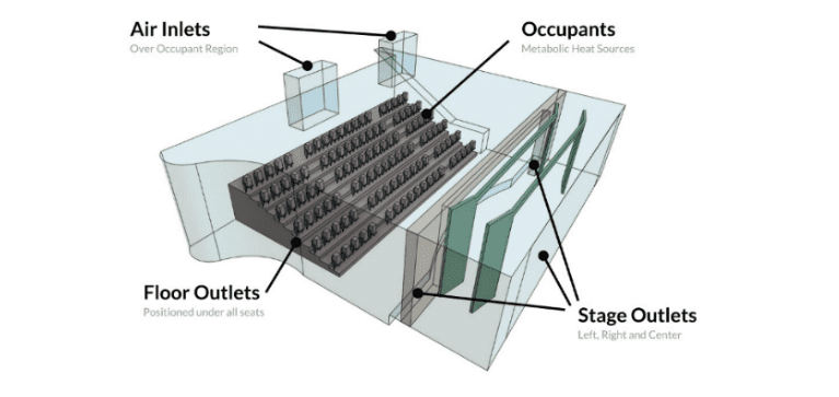
The second design goes into a completely different direction, the inlets were placed underneath the seats and at the stage floor (the outlets of the previous design), and two large outlets were placed behind the last row of occupants, in the room’s back wall. This kind of design was recently used in a large performance show’s room [3].
Simulation Results
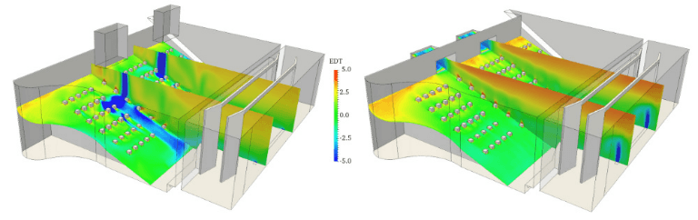
CFD simulation allows us to analyze the detailed aspects of both designs by visualizing the airflow velocity and direction, the air temperature, and the effective draft temperature (EDT), which combines the velocity and temperature information.
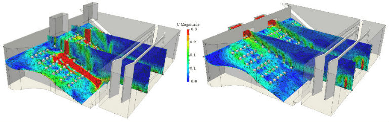
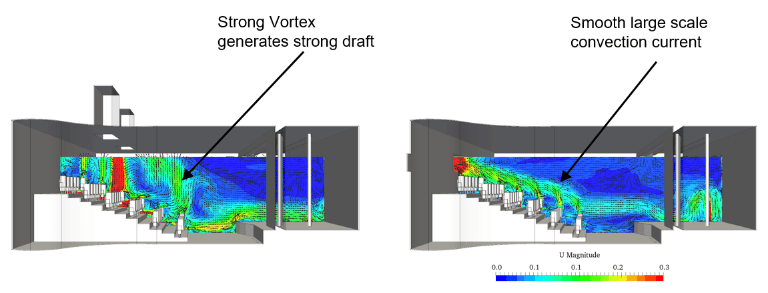
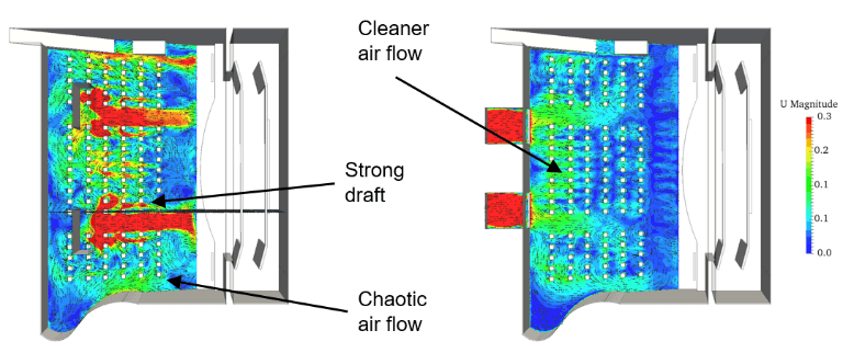
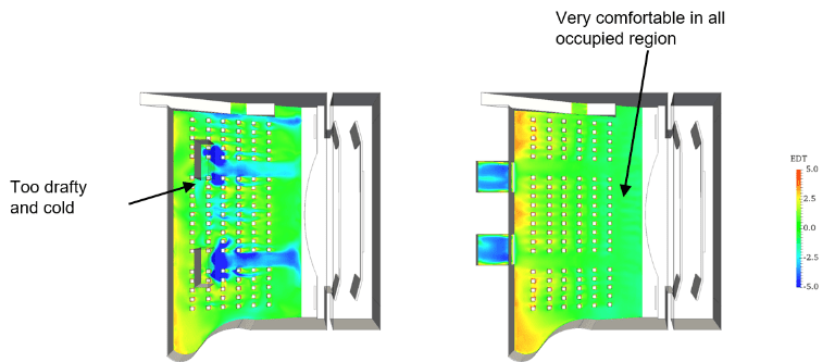
Air Velocity
Very strong drafts can be observed in the occupied region of the first design. The flow from the inlets is very poorly distributed through space, and the flow around the occupants is dominated by small-scale erratic vortices. The second design, however, reveals no strong drafts near occupants and a relatively large convection current renewing air near the occupied area.
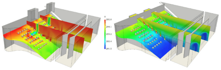
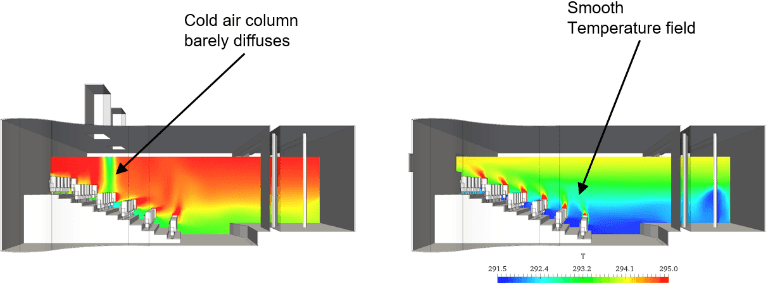
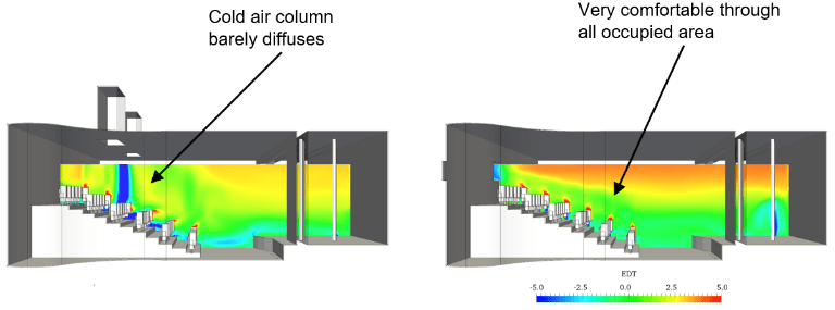
Temperature
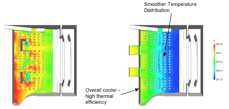
The simulation revealed large temperature differences throughout the occupied region, with some occupants getting exposed to very cold air. The thermal efficiency is also poor, as evidenced by relatively warm air. In the second configuration, all occupants are within the temperature comfort region, and the air temperature shows greater stratification.
EDT
In the first design, a large number of occupants find themselves outside the comfort standard (–3°F<EDT<+2°F). On the other hand, no discomfort can be observed for any occupant location, and occupants are well within the comfort limits.
Ashrae Standard 55 Conclusions
The simulation results reveal significant flaws in the first design, including strong drafts near the occupants, large differences in temperature across occupants, with many occupants seated outside of the thermal comfort zone. The area directly underneath the inlets is particularly thermally uncomfortable. The second design clearly shows a significant improvement; the air patterns are optimized and no drafts or large temperature gradients can be seen near the occupants.
Overall, the above post-processing images reveal vast differences between the two designs, with the second one being clearly superior in terms of thermal comfort. With a few simple modifications to the original ventilation system design, the overall thermal comfort was improved dramatically. The whole simulation took only a few hours of manual and computational time, but it allowed us to identify the flaws and test potential design improvements. Whatever design idea you might have—no matter how unconventional—with virtual prototyping you are only a few clicks away from predicting its performance.
Conclusion
Virtual simulation has been proven to be a valuable tool during any (and especially the early) design stage of a new space or building. While general best practices and personal experience still offer important and valuable guidance for the layout and design of spaces and HVAC systems, simulation helps to predict thermal comfort conditions with higher accuracy than ever before. Especially to avoid local discomfort and ensure proper dimensioning of ventilation systems, HVAC simulation needs to be a part of any design, and construction engineers’ tool kit.
When using ASHRAE 55 to assess the thermal comfort of your design, the outcome might be that thermal comfort simply can not be guaranteed for all accessible areas of a given space. It also depends on the expected clothing level and activity profiles of the possible occupants. This is still acceptable and simply has to be taken into consideration when allocating certain areas for different use types.
Generally, it’s unmanageable to satisfy everyone. Occupants are, and will always be, different, with varying perceptions of thermal comfort. This standard is based on data collected in laboratory and field study testing and simply provides a statistically optimized framework.
Other Thermal Comfort Resources from SimScale
- Whitepaper: Simulating the Indoor Environment
- Thermal Comfort and Radiation with SimScale
- Radiation and Thermal Comfort for Indoor Spaces
- Ensuring Thermal Comfort with HVAC for a School Building Design: Case Study Ramboll
- ASHRAE Standard 55 Thermal Comfort Assessment with Simulation
- How to Comply With EN 15251 and EPBD – Thermal Comfort & More


