
One of the most frequently asked questions by beginners to engineering simulation is how to learn finite element analysis, and how to use FEA software. This process is not easy, particularly if you want to learn by yourself, not in university. However, with a little motivation and direction, it is achievable.
In this article, we discuss the basic questions you have about FEA as a beginner, then lay out a learning path with books, papers, courses, and validation examples, whether you are coming to FEA as an engineer, designer, hobbyist, programmer, or mathematician.
FEA basics: what FEA does
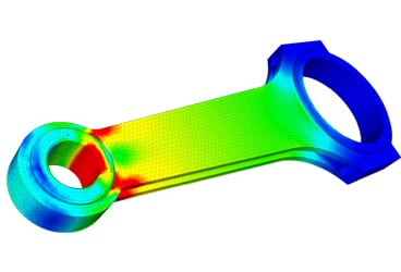
FEA is the acronym for ‘finite element analysis.’ Based on the finite element method (FEM), it is a technique that makes use of computers to predict the behavior of varied types of physical systems, such as the deformation of solids, heat conduction, and fluid flow. FEA software, or FEM software, is a very popular tool used by engineers and physicists because it allows the application of physical laws to real-life scenarios with precision, versatility, and practicality.
Engineers use this method to reduce the number of physical prototypes and experiments, and to optimize components in their design phase to develop better products, faster. To understand and learn FEA in depth, this “What is FEA” SimWiki article is a great resource.
How does FEA work?
FEA is the application of the finite element method (FEM) to practical problems. The finite element method is a mathematical procedure used to calculate approximate solutions to differential equations, allowing for its application to real engineering problems. The goal of this procedure is to transform the differential equations into a set of linear equations, which can then be solved by the computer in a routine manner.
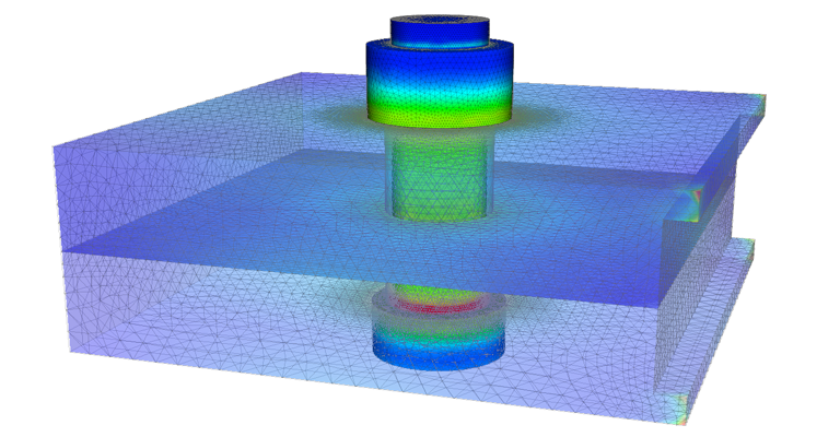
Differential equations are very important and present in many engineering problems because they represent the language in which physical laws are expressed. They connect changes in the internal variables of an object, such as displacement, temperature, or pressure, and their relation with the object’s geometry, physical properties, and external influences acting on it.
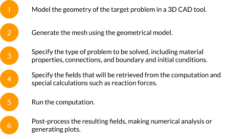
The detailed explanation of how this transformation from a physical law into a set of linear equations is performed is beyond the scope of this article, but here is a general overview of the process:
- The physical problem is well defined, with set physical laws to be applied, in the form of differential equations.
- The geometry of the object to be analyzed is defined, with the space occupied by it called the ‘domain’ and the surface enclosing it called the ‘boundary.’
- External influences acting on the boundary or domain are also well defined, such as forces, pressures, temperatures, or heat sources. These are known as ‘boundary conditions.’
- The ‘initial conditions‘ of the object are also well-defined. These are the set of values of all internal variables at the first moment of the problem, for example, initial velocities, pre-stresses, or the initial temperature distribution.
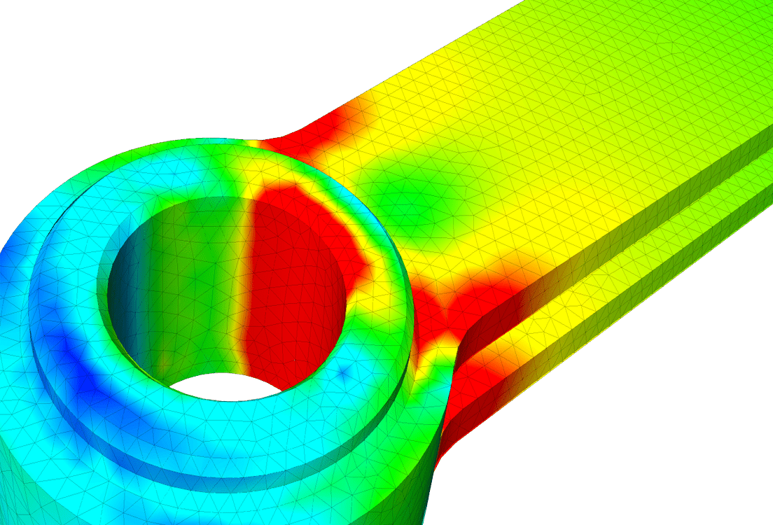
- The domain is then split into small basic shapes known as ‘elements.’ The set of all elements is known as the ‘mesh‘. Also, the points where neighbor elements meet are called ‘nodes.’ The size of the elements will determine the precision of the approximate solution, the smaller being the better. However, a higher number of elements used will increase the demand for computational resources such as memory and processor time.
- Then, all equations and boundary conditions are ‘projected‘ into the nodes, resulting in a finite—but often large—number of linear equations.
- The linear equations are solved by the computer, and the list of resulting variables for each node and element is written into files.
- The resulting data is used to make numerical analysis, visualizations and design decisions.
What are stress and strain?
Two very important concepts to grasp in order to start using FEA for structural assessment are stress and strain, as they are both related to the deformation of solid bodies. These topics are typically covered in depth when learning about the strength of materials, but here we will give a brief introduction.
When a solid body is subject to the action of external forces, such as pressure, contact, or gravity, the body will undergo some deformation. The shape and magnitude of such a deformation depend on many factors, such as the direction and magnitude of the external actions, the geometry of the body, and the rigidity of the constitutive material.
The simplest example of this is the deformation of a spring: when the spring is hung in a vertical position, it is in equilibrium with some characteristic length. If weight is attached to the lower end, the spring will extend, up until reaching another equilibrium point, this time with a longer length.
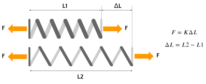
If the magnitude of the weight is varied, we will notice that the elongation of the spring is proportional to the weight, also known as Hooke’s law, and the constant of proportionality is known as the spring’s ‘rigidity.’
What is stress?
What happens internally, is that the external forces are balanced by forces developed inside the material, which tends to oppose the elongation effect, causing the equilibrium state. These internal forces are known as the material’s ‘stress‘ and are the result of cohesive forces at molecular levels. The higher the activity of the external force, the higher the stress developed by the material will be. Failure theories are based on limit stresses, that is, failure of the element is expected to occur when stress levels surpass a given threshold.
What is strain?
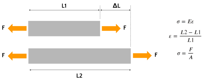
When trying to write Hooke’s law in terms of material stress, one notices that the elongation of elements is not a consistent measure. If the geometry of a test specimen (e.g., for a uniaxial test) is changed, then the rigidity constant does not generalize for a given material. A special measure of deformation should be considered. This is known as the material ‘strain‘ and has a few different definitions, such as ‘engineering strain‘ or ‘true strain.’ These definitions allow us to state a relation between the material’s stress and strain, using a measurement of the material rigidity known as Young’s modulus.
Although stress and deformation are the main calculations in FEA, they are not the only important predictions that can be made with it. Other very useful information for a given structural system that can be obtained with FEA include:
- Natural vibration frequencies and modes
- Forced vibration (harmonic) response
- Buckling limits and modes for thin structures
- Fracture propagation modes and fatigue life
For more information on stress and strain in FEA, read about principal stress and strain, the stress-strain curve, and how to calculate stress and strain.
What are some use cases of FEA?
Although the finite element method is not bound to a particular type of physical problem, its main field of application is the structural analysis of solids. Structural analysis might include different types of loading and scenarios, but its main purpose is one: to predict whether a given part or structure will safely withstand forces acting on it.
This is achieved—according to the theory of the resistance of materials—by looking at the state of the part in terms of stress and strain. The maximum values obtained by any method (for example, FEM) are compared to allowable values to see if they conform to the safety range. These allowable values are most of the time specified by a design code such as ASCE, ASME, Eurocode, etc.
Some typical use cases of FEA software include:
- Steel or reinforced concrete structures, for buildings and other civil applications, load lifting, etc.
- Industrial equipment, such as pressure vessels, piping, boilers, rotating equipment, etc.
- Manufacturing equipment, such as mills, molds, tooling, etc.
- Automotive, aircraft, or other transport structures, particularly for virtual crash tests.
What key industries use FEA?
Automotive
In the automotive industry, FEA software simulations are performed to assess the structural safety of designed components, such as chassis, anchors, suspension, bodyworks, etc. One of the most interesting applications is virtual crash tests, where a dynamical simulation is performed to predict deformations and energy absorption against crash impact. Here is a SimScale project simulating a car suspension’s deformation and stress.

For more information, see simulation for the automotive industry.
Industrial equipment
For industrial equipment design and engineering, finite element analysis (FEA) software is widely used. In the processing industry, for example, pressure and heat loads are applied to predict stress levels in piping, pressure vessels, tanks, and similar equipment. Another possible use for the industry is the simulation of forging processes for mills, benders, and stampers, to measure stress levels and spring-back magnitude of forged parts.
For more information, see simulation for machinery and industrial equipment.
Civil engineering and structural design
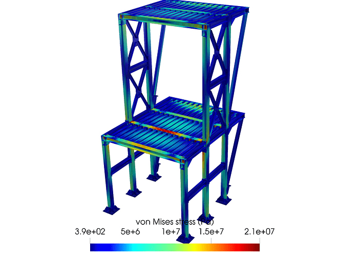
For civil engineering and structural design, FEA software has unleashed the power of fast and accurate analysis, with the possibility of automatically applying code load combos and checking compliance. Typical analysis scenarios include static loading, equivalent static loading, dynamic performance in seismic scenarios, natural vibration modes, and frequencies calculation. Here is an example project performing structural analysis on a steel structure:
For more information, see simulation for architecture, engineering, and construction (AEC).
Why is FEA important?
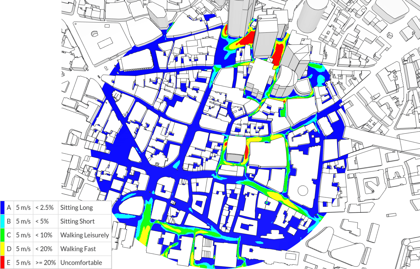
FEA is the defacto technology for detailed stress analysis and deformation prediction across almost every engineering field. As more analysis tools become accessible to designers and engineers, it has a lot of space to grow its presence. As we have been able to see, it is very versatile and powerful, making it a must-have tool in any product design portfolio.
The most recent trend in FEA software is cloud-native simulation services and tools. Companies such as SimScale provide simulation tools that run in the web browser and make use of remote servers for the computing tasks, freeing local resources, and lowering the requirement for powerful hardware and special software installations.
Run your first FEA in the browser
Set up your own cloud-native simulation via the web in minutes by creating an account on the SimScale platform. No installation, special hardware, or credit card is required.
How to learn FEA: start from your perspective
How you learn FEA depends on why you need it. There are several generic resources and guides available on the Internet, but most of these are based on the one-size-fits-all theory. Firstly, it is important to understand the perspective of the learner, whether the person is coming to FEM as a designer, hobbyist, engineer, mathematician or programmer. It is important to note that, in comparison with fluid mechanics problems, FEM software is more commonly used for solid mechanics problems.
- Engineers, designers, and hobbyists use FEA to make design decisions, so the priority is setting up problems correctly: geometry, meshing, materials, boundary conditions, and judging results.
- Programmers, developers, and mathematicians build or extend FEM itself, so the priority is the mathematics and mechanics behind the solver.
How to learn FEA as an engineer, designer, or hobbyist
For a professional engineer, designer, or hobbyist, the most important thing for learning FEA is to understand the right way to set up a problem. For someone using FEA from this perspective, an FEA software is a black box. Appropriate inputs are applied and corresponding outputs are analyzed to make design decisions. This corresponds to most of the industrial design departments where FEA is used.
With this in mind, it is essential to understand the pre- and post-processing aspects of the process in great detail. Any computer program runs on the philosophy of garbage in, garbage out (GIGO). Thus, if the inputs are not well understood, one will end up dealing with results that don’t make sense physically. In addition, the job description of most engineers or designers does not include debugging the backend FEA program, they are only required to use the results. This is why it’s even more important to be absolutely certain of the accuracy of pre-processing.
Creating the geometry or CAD model
One of the first steps is to create a reasonable geometry (or CAD model) that reflects reality as closely as possible. The geometry is generally simplified to create a computationally feasible and efficient model. A convenient way to create CAD models is to use tools like Onshape and Autodesk Fusion. Both of these tools are cloud-based and offer free access. Onshape’s free plan is for non-commercial use and keeps all documents public, while its Education plan is free for students and educators. Autodesk Fusion is free for eligible students and educators on a one-year license that renews annually, and a limited free license is available for personal, non-commercial use.
It is not always essential to start from the drawing board, however. CAD models can also be found on several public forums. One important word of caution when using CAD models from forums (such as GrabCAD) is to consider the small engravings made by authors. These engravings can significantly affect the mesh creation and need to be removed before using the models. Upon removal of engravings, it is essential to provide appropriate citations as required by GrabCAD download licenses. You can find some great tips in this YouTube video: “Preparing Geometry for Simulation“.
Pre-processing: Meshing and setting up the problem
Once the model is created, it needs to be discretized into elements. In other words, the geometry is divided into smaller parts, ensuring that the resulting PDEs are satisfied locally in each of the resulting small elements. For further tips related to meshing for structural problems, take a look at the blog article “How to Mesh Your CAD Model for Structural Analysis“. Similarly, the mesh generation can be found in the meshing documentation pages.
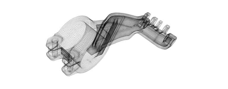
Once the model has been discretized, the parameters need to be provided. The model parameters include defining the relevant materials, constraints like contacts or rigid bodies, and assigning appropriate boundary conditions such as displacement and/or force boundary conditions.
The material can be linear, elastic or hyperelastic when large deformations are involved. In addition, inelastic effects like plasticity or viscoelasticity could also be demonstrated by the material. These aspects need to be taken into consideration and appropriately planned for. Some tips on modeling hyperelastic materials can be found in the following blog articles: “How to Choose a Hyperelastic Material Model” and “Modeling Elastomers Using FEM“. Additional tips on modeling inelastic effects can be found here: “Modeling Inelasticity with SimScale“.
In addition to the previously discussed issues, the material could also undergo damage or fracture. Many commercial software solutions provide limited features for these nonlinearities, and hence appropriate manuals need to be referred to when using such advanced features.
Finally, the boundary conditions need to be provided. In the majority of cases, displacement boundary conditions are preferred to force boundary conditions. This is primarily due to stability issues. In addition, nonlinearity in boundary conditions could arise from aspects like contact. Thus, appropriate contact models need to be assigned to the bodies or surfaces in contact. The state of the art is surface-to-surface contact using the penalty, Lagrange or augmented Lagrangian methods. A more detailed assessment of contact models can be found in the blog article on “Contact Mechanics and Friction“.
As discussed earlier, to learn FEA is not very popular among those who work with fluid mechanics. Fluid mechanics involves the advective/convective terms, which are the first-order terms in the Navier-Stokes equations. The presence of these terms reduces the stability of the solution, primarily at high wave numbers. Hence, the finite volume method (FVM) is preferred in fluid mechanics. However, as discussed in our article on “What is FEM?“, novel techniques have been developed as a modus operandi to overcome this problem and continue using FEM and FEM software. Nevertheless, these are two key aspects to consider when setting up a problem related to fluid mechanics. These are whether the flow can be considered laminar, or whether turbulence is important. Some tips and discussions on this issue can be found in the forum topic “Laminar or Turbulence“. If the flow needs to be considered as turbulent, it is vital that the right turbulence models are selected. Again, we recommend seeking further information in the referenced discussion on various turbulence models.
Once the problem parameters have been set up, it is important to choose the appropriate solvers. Parallel computing has become increasingly important in solving large problems of practical importance. In general, there are two main options: direct and iterative solvers. While direct solvers work well for smaller problems up to a million degrees of freedom, iterative solvers are more efficient beyond this. There are several sub-options possible among both classes depending on the platform that is being used for computation. For additional tips on choosing solvers for computing, refer to the blog article “How to Choose a Solver for FEM Problems: Direct or Iterative?“.
Post-processing
The final and most important step to help you learn finite element analysis is to post-process the results. SimScale has its own integrated online post-processor, and for offline work we recommend the open source tool ParaView, which can open results exported from SimScale. Some tutorials on post-processing can be found in the following YouTube videos:
- ParaView Basics Tutorial
- ParaView Detailed Tutorial
- Scientific Visualization Using ParaView
- Offline Post-Processing with ParaView
- Online Post-Processing with SimScale
In addition, we can also refer you to the blog article “Post-Processing of Aerodynamics with SimScale and ParaView” for more tips on using ParaView with SimScale.
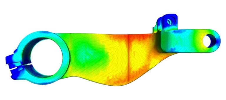
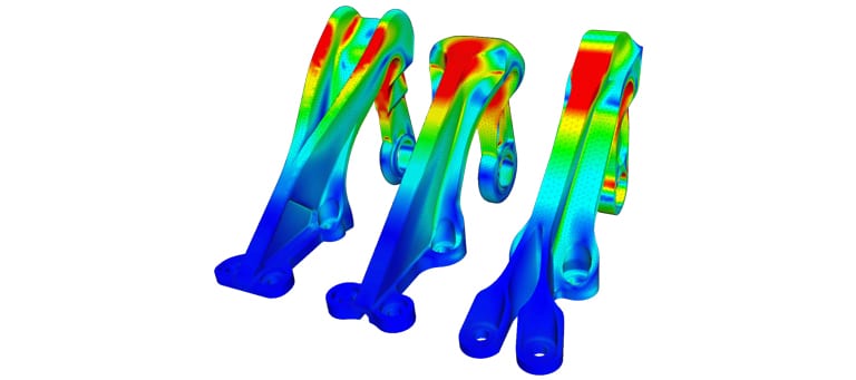
In most cases, people are happy to simply obtain a nice image of the simulation. But what separates a nice picture from a realistic simulation result? It is important to assess whether the simulation results and numbers actually make sense. For example, if the failure threshold for a material is 100 MPa, the stress on the material is 200 MPa, and the resulting picture looks pretty, then there is something wrong with the simulation. In reality, the material should have failed, but it is still carrying loads.
Impact analysis of a skull with and without a helmet
The purpose of a helmet is to protect the person who wears it from a head injury during impact. In this project, the impact of a human skull with and without a helmet was simulated with a nonlinear dynamic analysis. Download this case study to learn more.
Building domain knowledge: books for engineers and designers
This is where the domain knowledge comes in handy. A concise list of basic books to get a general domain knowledge include:
In solid mechanics:
- Strength of Materials by S. Timoshenko
- Theory of Elasticity by S. Timoshenko
- Non-Linear Elastic Deformations by R. W. Ogden
- Plasticity Theory by J. Lubliner
- Applied Mechanics of Solids by A. Bower (online form)
- Notes on Viscoelasticity by D. Roylance
In fluid mechanics and thermodynamics:
- Incompressible Flow by R. L. Panton
- An Introduction to Fluid Dynamics by G. K. Batchelor
- Modern Compressible Flow by J. Anderson
- Elements of Gas Dynamics by H. W. Liepmann and A. Roshko
For the more experienced engineers and designers who would like to get an engineering perspective on finite element analysis, some helpful reads include:
- The Finite Element Method: Its Basis and Fundamentals by O. C. Zienkiewicz and R. L. Taylor
- A First Course in Finite Elements by J. Fish and T. Belytschko
- The Finite Element Method: Linear Static and Dynamic Finite Element Analysis by T. J. R. Hughes
- Textbook of Finite Element Analysis by P. Seshu
All of the above books discuss linear FEM primarily. There is no one perfect reference book that suits every language and interest. Since nonlinear FEM does require a deeper insight into the topic, it will be discussed further in the upcoming section.
To read more about finite element analysis and the theories supporting it, check out the FEA section of the SimWiki, where you can find more articles related to computer-aided engineering.
How to learn FEA as a programmer, developer, or mathematician
This part of the article addresses the interests of programmers, developers, and mathematicians who want to learn finite element analysis. The main interest for those who find themselves in this category is to develop their skills in the finite element method, including the development of new methods, elements, material models, etc. Thus, it is necessary for these learners to completely understand how FEM works. This section will address resources related to the black box.
Mathematical and domain-related preliminaries
In the last section, the emphasis was on the pre- and post-processing regimes. In contrast, this section will focus on providing resources related to how FEA works in the background. To learn FEA, you need a solid understanding of the related mathematics, including linear and tensor algebra, differential and integral calculus, complex numbers, etc. In addition, continuum mechanics forms the basis of all mechanical engineering related problems. A thorough understanding of continuum mechanics is a mandatory pre-requisite to understanding and mastering FEA. The two-volume and freely available treatise by Prof. Rohan Abeyaratne on this topic serves as an excellent starting point for this venture.
- Volume 1: A Brief Review of Some Mathematical Preliminaries
- Volume 2: Continuum Mechanics
Another particularly good reference connecting continuum mechanics to finite element analysis is the book “Nonlinear Continuum Mechanics for Finite Element Analysis” by J. Bonet and R. Wood.
In addition, at the very minimum, a basic understanding of functional analysis, variational methods, and tensor calculus is mandatory for most programmers and developers. Of course, for mathematicians who learn FEA, this is their bread and butter, and they should find the material familiar. An excellent book for engineers who want to understand the terminology used in the finite element literature can be found in “Introductory Functional Analysis: With Applications to Boundary Value Problems and Finite Elements” by B. D. Reddy. Some other useful resources with regard to these mathematical preliminaries include:
- Ordinary Differential Equations by G. F. Carrier and C. Pearson (provides a rigorous treatment of ordinary differential equations and solution methodologies)
- Elementary Vector and Tensor Analysis for Engineers by R. M. Brannon (a free online text)
Moreover, good repositories of knowledge on linear finite elements and detailed treatment of involved mathematics can be found in:
- Finite Element Procedures by K. J. Bathe (serves as a general reference)
- An Introduction to the Finite Element Method by J. N. Reddy (provides further citations to many other texts and literature)
- The Finite Element Method: Volume 2 Solid Mechanics by O. C. Zienkiewicz and R. L. Taylor (a detailed treatise that could be of interest to civil and mechanical engineers)
References in advanced topics of FEM
Once these basic pre-requisites to learn finite element analysis have been completed, there are three more outstanding books and references in the area of nonlinear mechanics:
- Nonlinear Finite Element Methods by P. Wriggers
- An Introduction to Nonlinear Finite Element Analysis by J. N. Reddy
- Nonlinear Finite Elements for Continua and Structures by T. Belytschko, W. K. Liu, and B. Moran
Each of these texts presents the ideas of nonlinear mechanics in their own unique fashion. There is no one best book here, and learners must adapt to whichever one provides the most familiar notational and mathematical reading.
In addition, in the area of inelastic problems related to plasticity, viscoelasticity or creep, the book “Computational Inelasticity” by J. C. Simo and T. J. R. Hughes has remained an authority for over two decades. The pioneering work of Simo and co-workers remain state of the art in the area of simulation of the inelastic phenomenon.
Moreover, specialized topics—such as using FEA in contact—are examined in detail in separate texts. The mathematical understanding of mixed methods—commonly used in areas like contact mechanics—is by itself a topic of detailed study. A good beginner book for computational contact mechanics is “Introduction to Computational Contact Mechanics” by A. Konyukhov and R. Izi. Two other texts on computational contact mechanics for advanced readers include:
- Computational Contact Mechanics by P. Wriggers
- Computational Contact and Impact Mechanics by T. Laursen
Both the above texts are mathematically intensive and require a thorough understanding of tensor calculus and curvilinear coordinates. Furthermore, reference texts related to the application of FEM in the areas of fluid mechanics and heat transfer include:
- The Finite Element Method: Volume 3 Fluid Dynamics by O. C. Zienkiewicz and R. L. Taylor
- The Finite Element Method in Heat Transfer and Fluid Dynamics by J. N. Reddy and D. K. Gartling
Finally, some books of interest to mathematicians include:
- Finite Elements: Theory, Fast Solvers, and Applications in Solid Mechanics by D. Braess
- Mixed and Hybrid Finite Element Methods by F. Brezzi and M. Fortin
- Mixed Finite Element Methods and Applications by D. Boffi, F. Brezzi, and M. Fortin
Finally, if one intends to write his or her own FEM code to understand the intricacies, two excellent hands-on references include:
- Programming the Finite Element Method by I. M. Smith, D. V. Griffiths, and L. Margetts
- MATLAB Guide to Finite Elements: An Interactive Approach by P. Kattan
Online courses, tutorials, and validation examples to learn FEA
More detailed courses to help you learn finite element analysis can be found on several websites including:
- SimScale tutorials and webinars
- NAFEMS courses range from beginner to advanced and are related to modeling problems in all areas
- iMechanica forums mostly serve the solid mechanics community
- Read more about FEA on the web: FEA for All, Stress eBook, or the SimScale blog
As discussed earlier, it is important that the developed methodologies and programs are validated with standard problems. This is what differentiates a pretty picture from an accurate simulation. Some good sources for validation examples include:
- SimScale validation cases
- NAFEMS publications
In addition, top computational mechanics journals provide an excellent source of information on the current state-of-the-art research in these areas. They also provide validation examples and sources for comparison for problems involving finite element analysis. Some of the top journals in the area of FEA include:
- Computational Mechanics
- Computational Materials Science
- International Journal for Numerical Methods in Engineering
- Computer Methods in Applied Mechanics and Engineering
- Journal of Fluid Mechanics
- Journal of the Mechanics and Physics of Solids
- Extreme Mechanics Letters
How can I learn FEA with SimScale?
To put your knowledge into practice as soon as you learn FEA, SimScale provides an easy to use, cloud-based FEM software platform that provides an interactive interface suitable for FEM simulations. If you are interested in FEA software and want to start leveraging its benefits in your projects, you can make use of the following resources:
- Sign up for a free SimScale account by clicking on Start simulating now below, where you can set up your simulations in just a few minutes and get real-time support from our experts and engineers.
- Read the SimScale FEA Documentation.
- Work through the blog article “9 Learning Resources to Get You Started with Engineering Simulation” and the SimScale tutorials.
Frequently asked questions
FEA splits the geometry of an object (the domain) into small elements connected at nodes, applies boundary conditions such as forces, pressures, or temperatures, and turns the governing differential equations into a large set of linear equations that a computer solves. For structural problems, the key results are stress and strain, which are compared against allowable values to check whether a part will safely withstand its loads.
Start from your perspective. Engineers, designers, and hobbyists should focus on setting up problems correctly: geometry, meshing, materials, boundary conditions, and judging whether results make physical sense. Programmers, developers, and mathematicians should study the mathematics behind the solver, including linear and tensor algebra, calculus, continuum mechanics, and functional analysis. In both cases, practice on real simulations and check your results against validation cases.
Using FEA software to make design decisions is achievable without a university course if you understand strength of materials and learn pre- and post-processing in detail. Developing FEM methods, elements, or material models is harder, because it requires a thorough understanding of continuum mechanics, tensor calculus, and functional analysis.
Yes. Free resources include the SimScale SimWiki, documentation, tutorials, and validation cases, Prof. Rohan Abeyaratne’s freely available continuum mechanics volumes, A. Bower’s Applied Mechanics of Solids online, and the iMechanica forums. You can practice on a free SimScale Community account, which runs in the web browser with no installation or special hardware.
To learn how FEA works in the background, you need linear and tensor algebra, differential and integral calculus, and complex numbers, plus continuum mechanics. Programmers and developers also need a basic understanding of functional analysis, variational methods, and tensor calculus.
The purpose of this article was to provide you with all the resources you’d need to learn finite element analysis even as a beginner. The more experience you have with FEA software, however, it is important to filter them and find the ones that help improve your own skills. Good luck! It’s a journey worth making!
If you’d like to learn more about the SimScale cloud-based platform and its capabilities for FEA, watch one of our recorded webinars.
Start learning FEA with SimScale
Set up your own cloud-native simulation via the web in minutes by creating an account on the SimScale platform. No installation, special hardware, or credit card is required.