FEM software users often wonder how stress and strain are calculated, and how these quantities are related to the nodes. Which of these are calculated first? An ad-hoc answer to the question is strain. However, the real answer is neither. Confused? In short, a FEM software calculates the displacements and reaction forces at the nodes. This is later used to calculate the strains and then the stresses. If you’re wondering what exactly the finite element method is and how to learn it, I recommend that you read these two blog articles: “What is FEA?” and “How can I learn FEA?”
In order to understand how and when stress and strain are calculated, it is important to first understand how FEA software—including SimScale—functions. Most FEM software solutions have a similar workflow, which is imperative for knowing how and when quantities are calculated.
Stress and Strain Mathematics of the Solution Process in FEA
Originally, computers were designed to solve matrix equations. Numerical techniques have been developed over the last several decades with the goal of solving linear and nonlinear matrix equations. Today, one can say that linear systems can definitely be solved. However, the same cannot be assumed for a nonlinear system of equations.
In addition, one of the aspects of efficient meshing includes assignment of node numbers such that the total bandwidth of the matrix is reduced to a minimum. Thus, equation systems are commonly stored in “Sparse” formats. For more details on sparse matrices and solvers, the blog article on “Direct and iterative solvers” is a recommended reading. An entire branch of applied mathematics is dedicated to improving solvers and algorithms for solving nonlinear system of equations.
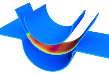
The purpose of a helmet is to protect the person who wears it from a head injury during impact. In this project, the impact of a human skull with and without a helmet was simulated with a nonlinear dynamic analysis. Download this case study for free.

FEA Stress & Strain The Process of FEA
So far, it is understood that FEM converts a PDE into a system of equations. This system of equations (in matrix form) is solved using complicated algorithms and solvers. The question remains as to what is one solving for? Is one solving for displacements or velocities or strains or stresses or forces?
In short, we are generally solving for unknowns at the nodes. In mechanical problems, these unknowns are commonly displacements, and in thermal problems, the unknown is usually temperature. Further quantities like stress and strain are obtained only as part of post-processing. The overall process of FEA can be divided into several steps:
- Preparation of geometry
- Pre-processing
- Post-processing for outputs
- Analysis
In the coming section, each step involved in an FEA program and when/how stress and strain are calculated will be discussed in more detail. The overall procedure remains the same, irrespective of the software used.
Preparation of Geometry
The preparation of geometry is referred to as development of a CAD model. Most often, CAD models can be obtained through online platforms like GrabCAD. The considered CAD model needs to be a good representative of the reality. It is important to be cautious, as many of the models obtained from such forums have engravings. The original authors often engrave their name on the CAD model, and the presence of such engravings can cause issues with automatic mesh generators, which leads to extremely small or distorted meshes and subsequently errors in the solution.
Pre-Processing
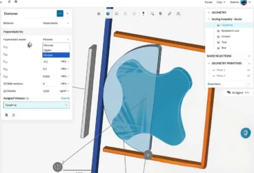
Pre-processing involves several important issues, which start from meshing. SimScale offers automatic mesh generators, including the possibility for mesh refinements in layers or at regions around possible singularities.
The mesh creation is an integral part of preparations for the solution process. Meshing also implies to choosing an interpolation function. For example, as discussed in the blog article on “Modeling Elastomers Using FEM: Do’s and Don’ts,” second-order interpolation functions are preferred over first-order—especially for modeling hyperelastic materials. In contrast, using first-order tetrahedrons can be disastrous! Hence, choosing the right mesh and interpolation type governs the accuracy.
In addition, pre-processing also involves choosing the appropriate boundary conditions, material properties, and constraints when selecting a mesh.
Solution Process
The PDE governing the physics has been converted to an integral form and later was converted into a matrix form. The matrix contribution of each element is calculated and assembled into a global system of equations. This global equation is eventually sent to a solver, which takes the equation for nodal displacements and reactions. While in linear problems, the solver solves for the displacements and reactions in one step, while the nonlinear problems need several iterations to solve for the same.
Once the nodal displacements have been solved, it is time to calculate the stresses that are shown for plotting. A flag is generally used to inform the routine that the solution process is complete and stresses are being calculated for plotting.

FEA Stress Analysis Stress Projection Process
The stresses are calculated at each of the integration points in the element and later projected to the nodal points, as illustrated in Fig. 03.
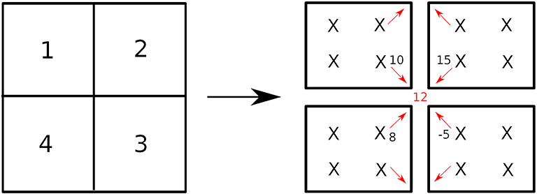
Fig. 03 illustrates a simple case of a four-noded quadrilateral element with 2×2 quadrature scheme. Irrespective of the type of element and integration scheme used, the overall procedure remains the same and the displacements are known at the nodal points. Using the interpolation (or ansatz or shape) functions, the displacements are first calculated at the integration points.
Following this, the kinematic quantities, like strains and deformation gradients, are calculated at the Gauss point. Then, using these kinematical quantities and material properties, the stress is calculated at the Gauss point. Following this, using the interpolation function for that element, this stress is projected to the nodes.
Now, as shown in Fig. 03, each projection might lead to slightly (or even completely) different values of stresses at the node. Most FEA programs perform a nodal averaging so that the projected values are averaged and only one value is considered for each node. This is shown in red in Fig. 03.
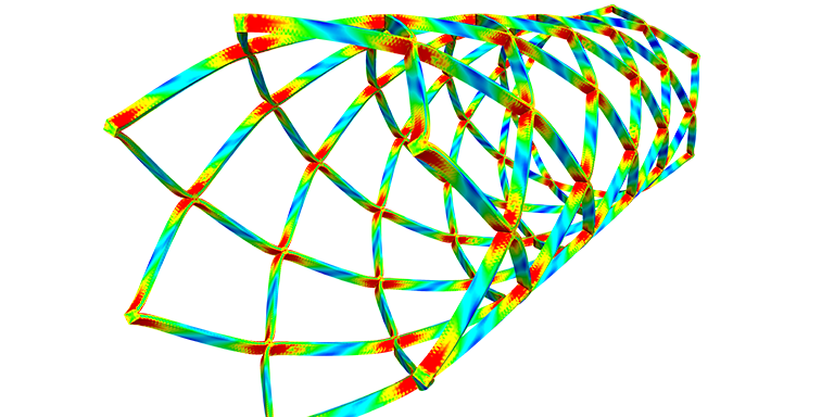
Caution needs to be demonstrated, as frequently—especially in fracture problems—displacement plots are discussed rather than stresses. However, due to the above averaging, stresses might appear smooth, there might be significant jumps, and the mesh might not be good enough to obtain stress convergence. While averaging is a nice tool for colorful pictures, switching off averaging could demonstrate whether the mesh leads to reasonable results.
FEM Software Conclusion: Calculating Stress and Strain with FEM Software
To summarize the discussions, displacements and reaction forces are the fundamental quantities that are being solved in any FEM computation. Both stresses and strains are calculated as post-processing quantities once a converged solution is obtained for the nodal displacements.
Stress and strain are calculated at the Gauss points and further on projected to the nodal points. In this scenario, it is vital that extreme caution is exercised since most FEM software solutions perform a nodal averaging. Such averaging will disguise any mesh effects that need to be addressed for accurate solutions.
I hope this article helped you better understand stress and strain. If you’d like to put your knowledge into practice, SimScale offers the possibility to carry out finite element analyses in the web browser. To learn about all the features provided by the SimScale cloud-based simulation platform, download this document.