Formula One is an exciting sport and has a strong following. An F1 car in itself is a marvel of mechanical engineering. On a top-speed straight, a Formula One car attains sufficient speed to take flight, if not for the downforce that holds it down. The front wing and rear wings play a critical role in the overall aerodynamics of an F1 car. 2017 brought about drastic changes to the regulations that would increase the aesthetics of the car and decrease lap times by up to 5 seconds. The video by motorsport.com visually shows the changes between 2016 and 2017.
This article looks at the design of the front wing of an F1 car and possible ideas for improving the overall aerodynamics using CFD. To do so, it is first important to understand the regulation changes.
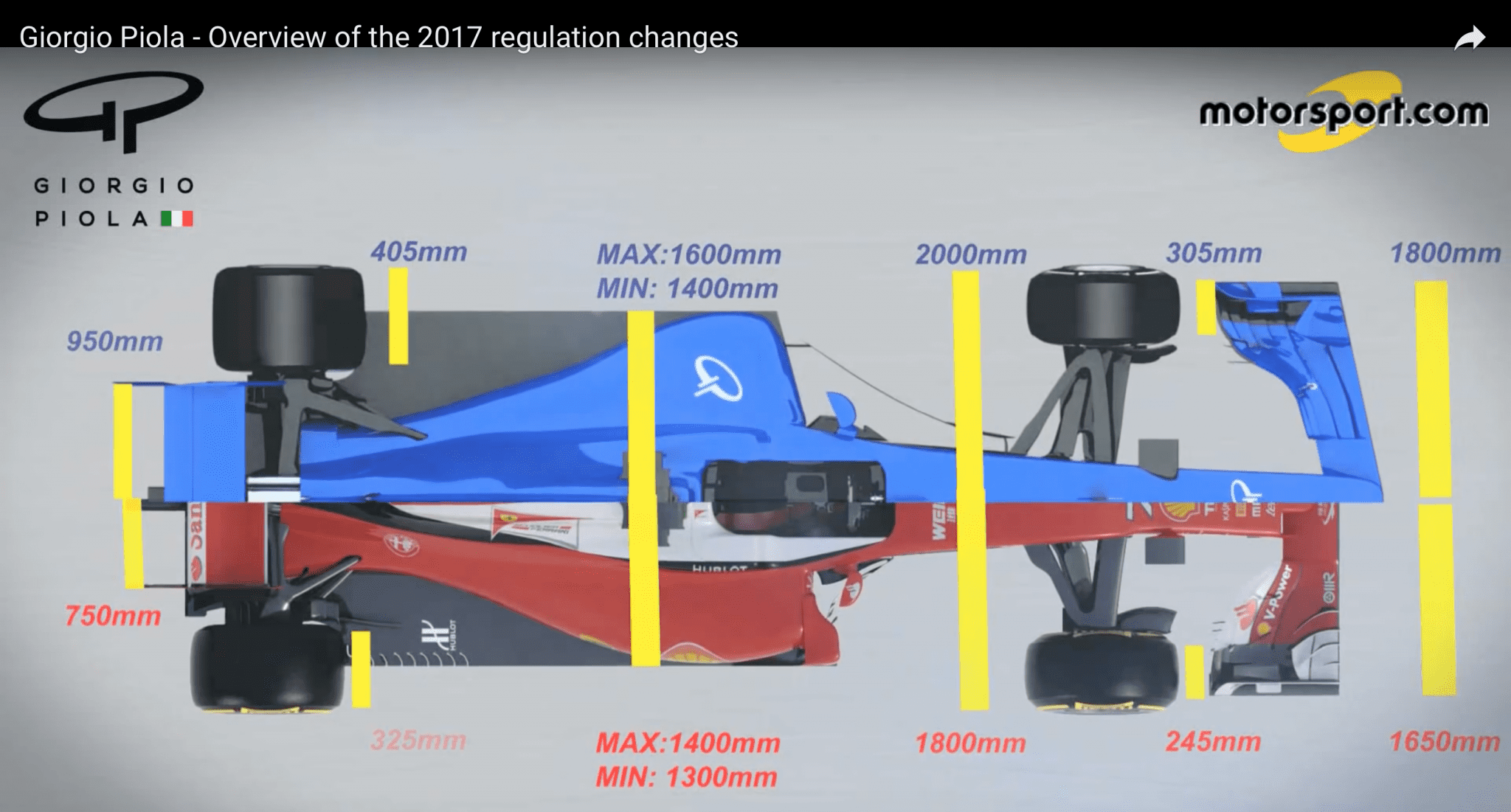
F1 Front Wing Change in F1 Regulations: 2016 and 2017
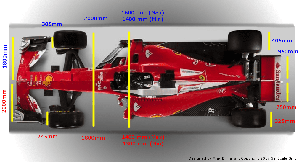
Figures 1 and 2, based on the video by motorsport.com, visually depict the differences in dimension regulations of 2016 and 2017.
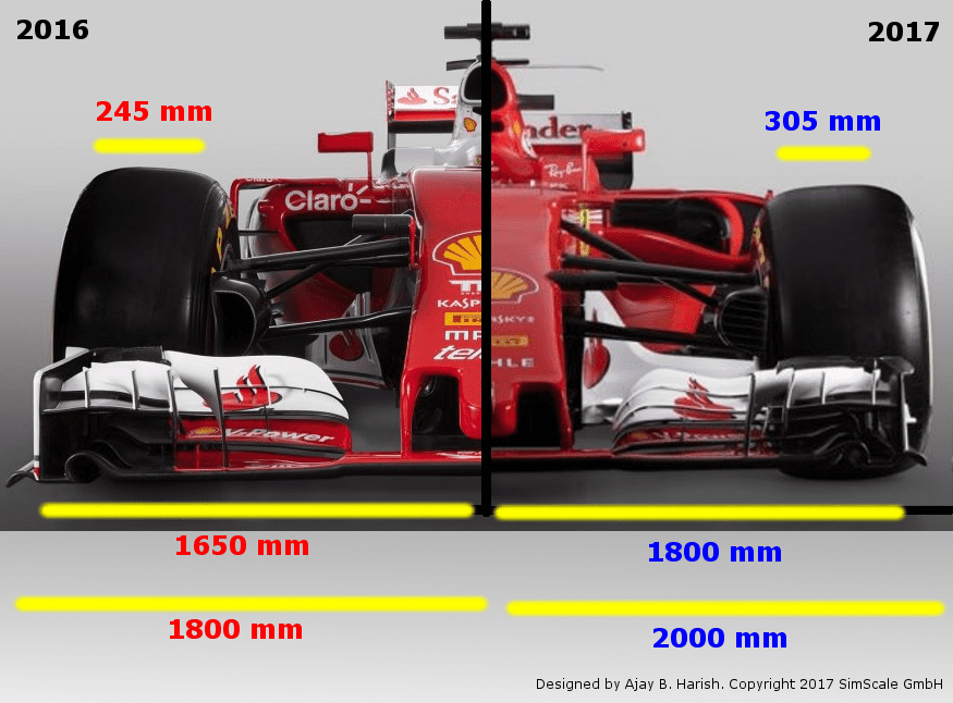
Figures 1 and 2 show the main change between 2016 and 2017—the change in the dimension of the F1 car’s front wing from 1800 mm to 2000 mm.
The Formula One season 2017 is marked by a massive change of technical regulations with wider tires, bigger wings, and much more downforce. In this on-demand webinar, we will put you in the seat of an aerodynamics engineer and investigate the impact of the new car design on its aerodynamics, using fluid flow simulations to understand the behavior of the flow around the car. Watch the webinar recording by simply filling out this form. It will play automatically.
For more extensive details on the regulations, we can re-direct you to the regulations part on the FIA website.
F1 Aerodynamics Aerodynamic Design of a Formula One Car
Aerodynamics plays a fundamental role in the overall setup of a Formula One car. An air duct panel between the front wheel and the side panel, for instance, can add more speed than two or three extra horsepower. The teams invest as much as up to 20% of their total budget in understanding the aerodynamics of the car. Modern F1 cars can drive corners much faster than normal, commercial cars, and this would not be possible without downforce.
Meticulous precision work is undertaken using computations and experiments in wind tunnels to accurately tailor the wings and the wind deflectors to the last millimeter. This design is aimed at increasing the downforce and reducing the drag. This also permits shorter braking distances and higher cornering speeds. The downforce generates 80% of the grip required for the car. F1 cars can withstand centrifugal forces of up to 4G without sliding off the track primarily due to the aerodynamic designs allowing high cornering speeds. This would be impossible without downforce and thus ensures performance and safety.
But downforce is not the only aspect that needs to be optimized. There is no one particular design that works for all circuits. Depending on the speed and type of the circuit, different configurations are ideal. There are more than 20 settings in the rear wing and over 100 settings in the front wing. However, there is only one ideal condition. The teams need to adjust the configuration for an ideal performance in each race and the team that gets closest to that ideal conditions wins.
For example, the Italian Grand Prix in Monza has long straights and fast corners, and it is considered a high-speed circuit. Here, the teams use flat wings to gain the highest possible speeds. In contrast, in circuits with lots of narrow corners (like Monaco), wing elements with a steep setting are used. This helps generate the maximum possible downforce for the cars to drive through the corners faster. Though it is commonly believed that the front wings are responsible for about one-third of the downforce, this can get drastically reduced to one-tenth if there is a car directly ahead. Apart from the front wing, about half of the downforce is due to the diffusers on the vehicle’s underbody. These lead the flowing air towards the rear, creating a strong suction effect.
Most large F1 teams have wind tunnels to experiment with. CFD simulations offer an excellent alternative to that, allowing teams to reduce their experimentation and associated costs, while accurately tuning the parameters using computational models.
F1 Front Wing Design Importance of Front Wing in an F1 Car
Before proceeding, it is extremely important to understand the role of the front wing in a Formula One car. The front wing works in the opposite way of how an aircraft wing works. While an aircraft wing produces lift, the front wing produces downforce to keep the car from taking off. In other words, the airfoil of a front wing is profiled so that it helps keep the car on the ground and wheels in contact with the surface. Thus, it plays a major role in ensuring sufficient grip and traction for the car.
In addition to controlling the downforce, the front wings also control the total airflow around the Formula One car. Being the first part of the car that the air comes in contact with, the front wing also governs the overall aerodynamics of the F1 car. Another function is to direct the airflow in a way that is optimized for the aerodynamics of the car. Just to get an idea of the contributions to downforce and drag, we can direct you to the article on “What parts of a Formula 1 car generate the main aerodynamic forces?“.
Front Wing Design
The front wing is designed in a shape that is opposite of an airfoil. Can you guess why? Yes, to prevent it from taking off! The front wing (or the main plane) is suspended from the nose and runs along the entire length of the Formula One car. To this main plane, adjustable flaps are attached, and at the ends of the main plane, the endplates are attached. The different parts of the front wing are shown marked in Figure 5.
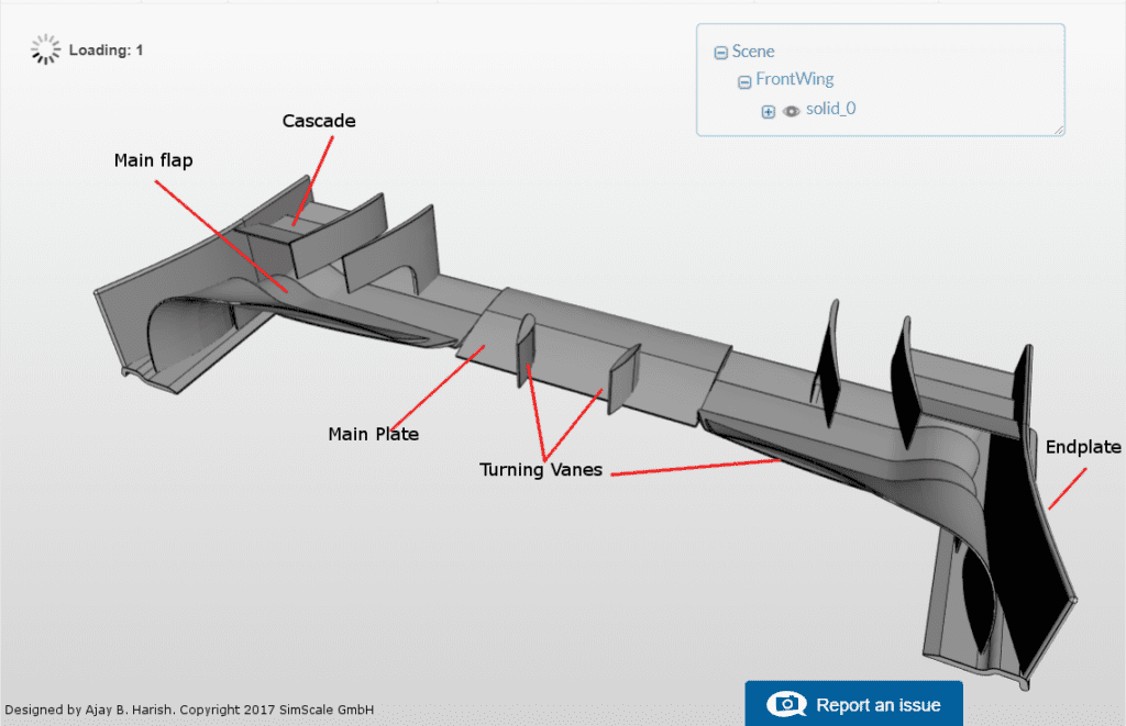
The main flaps and the endplates make sure that the wind flows above and beneath the airfoil. The endplates especially play a part in redirecting the airflow around the tires that are aerodynamically bad.
Endplate Design
Endplates are one of the most important aspects of the front wing. The optimization of their position and shape can significantly improve the overall aerodynamics. The endplates have 5-10 times more effect than most other parts. They control the flow of air around the Formula One car by redirecting the airflow around the tires. This minimizes the overall drag resistance produced and facilitates the airflow to continue back to the side pods and the car floor.
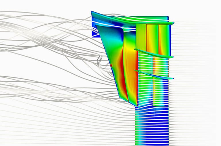
Over the years, there have been several changes, and at present, the wheels are much closer to the chassis than several years ago. In addition, the tips of the front wings coincide with the ends of the tires. This creates unnecessary turbulence in front of the wheels and increases drag. Hence, the inside edges of the end plates are curved to ensure that the air flows around the tires. Figure 6 shows the airflow around the endplate.
In addition, the endplate stops the high-pressure air on the top of the wing from rolling over the wing to the low-pressure air beneath, causing an induced drag. This is also an aspect to watch out for during the simulations. Similarly, the endplates do not allow “turbulent” air created by the front tire to get under the floor of the car. To further assist in the functionality of the endplates, some Formula One cars also use vertical fences—called splitters—attached to the undersurface of the front wing.
Tip 1: For great performance, ensure that the endplates minimize the airflow from top to the bottom of the car. Do the endplates also facilitate the air to flow around the wheels?
Wing Flaps
The wing flaps on either side of the nose cone are asymmetrical so that their height is lesser near the nose cone. This arrangement facilitates the air to flow into the radiators and to the underfloor. If the height of the wing flap is the same as the nose cone, it would reduce the overall air to the radiators and thereby lead to a rise in engine temperatures.
The asymmetrical shape also allows better airflow to the underfloor and the diffuser, increasing downforce. The wing main plane is—in accordance with the FIA rules—flat in the center, and the same design is required for all cars. This again allows slightly better airflow to the underfloor aerodynamics, but it also reduces the wings’ ride height sensitivity. The main area of development is the wing profile interaction with the front wing endplate.
Tip 2: How do the changes in the front wing profile and endplate affect the airflow profiles around/on each other?
Simulating an F1 Front Wing Flow Control Techniques
We looked at the effect of each of the front wing elements on the overall aerodynamic balance of the Formula One car. Yet, the elephant in the room remains unaddressed—”All the theory sounds great but what elements could we use to make it better?” Some elements that could be considered to alter the flow field include vortex generators, blowing/suction elements, and moving surfaces.
Vortex Generators
These are the first fixes for any flow problem. They try to modify the flow by redistributing the overall momentum. The fluid with high momentum is brought into the boundary layer. Below is an interesting YouTube video with a more detailed explanation of how vortex generators work.
Concisely, VGs prevent flow separation. They are generally around the height of the local boundary layer and are usually placed at around 20 times the local boundary layer height ahead of the point of separation. They can be used to generate vortex suction, add downforce, and help guide the flow.
Blowing/Suction Elements
Blowing can be used to inject high-energy air into the boundary layer, and suction can be used to remove the tired boundary layer. These are not widely used due to the power requirement and additional weights. Yet, both of these are very interesting ideas that can be used effectively to reduce drag through careful design of the blowing/suction slot. Some of the most famous ones are the McLaren F-duct, Lotus drag reduction, and Red Bull S-duct.
Moving Surfaces
Moving surfaces have not been used so far on the front wing, but they are definitely an idea for the future. The idea rests on creating a surface that moves at the same speed as the flow, thus reducing the relative motion. This could be an extreme way to manage the flow. Yet, the introduction of new innovations each year is what keeps the sport interesting through reduced lap times, more feasibility for overtaking maneuvers, etc.

Explore CFD in SimScale
F1 Front Wing Conclusion
The greatest shortcoming of CFD simulations has been to estimate the wake (or turbulent behavior) accurately. For example, one of the trickiest tasks is modeling the wake between the front wing and the tires. Ensuring good discretization and accurate turbulent models in regions of interest could govern the accuracy of the predictions made using CFD. The front wing design, development, and optimization are not just about adding downforce but, more importantly, about cleaning the airflow toward the rest of the Formula One car and providing crucial stability when turning through corners.


