SimScale offers engineers a fast and accurate electrical motor design software in the cloud. Access to simulation tools is critical at all design stages to minimize design performance issues at a later stage of product development. Common analysis types used by engineers include structural finite element analysis (FEA), vibration and modal analysis, heat transfer, and computational fluid dynamics (CFD). SimScale offers all of these analysis types in one easy-to-use tool with a simple yet powerful user interface. An engineer working on a new product or component, can easily import and edit their CAD model in SimScale and more importantly, perform multiple analysis types using intuitive, automated workflows for simulation setup, meshing, and results post-processing.
This article describes the structural assessment and vibration analysis of an electric motor support bracket to calculate and verify if its critical response frequencies lie within the intended operating range. In addition to the vibration analysis, we show engineers how to perform a load analysis on the electric motor shaft under an applied torque. The design goal of this simulation study is to optimize the electric motor support bracket to ensure that its eigenfrequencies remain outside of the motors’ operating speeds, avoiding possible part damage, bolt loosening, and reduction in clearances between parts and unwanted noise. In many cases, there is a danger that resonance effects might excite vibrations in the support bracket or other components. Meticulously analyzing this uncertainty is needed to reduce the risk of unwanted issues and, simulation at the early stages provides this guarantee. Geometry changes are made to mitigate dangerous vibration at shaft speeds close to the calculated first eigenfrequencies of the support bracket. Note, that the motor in question has a fixed rotational speed. Vibration analysis is even more important when variable speed drive motors are used for example and more in-depth studies are needed in those cases. We can also perform a quick safety factor check of the motor shaft under an applied torque to represent real-world loads and ensure a minimum safety factor of two is validated under normal operating conditions. A factor of two is a good starting point as it means the stresses are half of the yield stress of the shaft material (mild steel), which is getting close to the material endurance and performance limits that affect fatigue and component life. The entire engineering simulation workflow is implemented via a web browser and performed in the cloud.
Fast and Accurate Structural Simulation
The FEA capabilities in SimScale enable engineers to virtually test and predict the behavior of structures and components, and to solve complex engineering problems subjected to static and dynamic loading conditions. SimScale uses scalable numerical methods that can calculate physical variables otherwise very challenging due to complex loading, geometries, or material properties. Another structural analysis software feature, modal (frequency) analysis can help determine the eigenfrequencies (eigenvalues) and eigenmodes (mode shapes) of a structure due to vibration. The results are important parameters to understand and simulate structures and products that are subject to unsteady conditions. The resulting frequencies and deformation modes are dependent on the geometry and material distribution of the structure, with or without the displacement constraints. A static analysis type allows time-invariant calculation of displacements, stresses, and strains in one or multiple solid bodies and the results are a consequence of the applied constraints and loads. SimScale has integrated the Code_Aster solver into the platform for frequency and static analysis simulations. A much broader study can use a multidisciplinary physics approach to simulate and optimize the loading, modal, thermal, and rotating aspects of the electric motor. In this example, we will focus on the vibration analysis of the electric motor support bracket and load stresses on the motor shaft.
Vibration Analysis of an Electric Motor Support Bracket
A simple workflow is required to complete the analysis for both the support bracket and shaft.
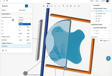
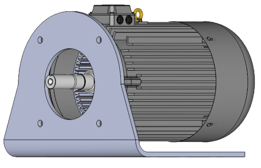
Import CAD – Users can import many types of common CAD file formats and use CAD connectors with tools such as Onshape, Solidworks, AutoCAD, and more. The feature CAD mode in SimScale allows users to perform basic CAD operations for editing without leaving the platform. The motor geometry is imported from Onshape. The number of faces increases with support bracket geometry modifications with a total of six bracket CAD variants defined. The motor shaft is also a single volume.
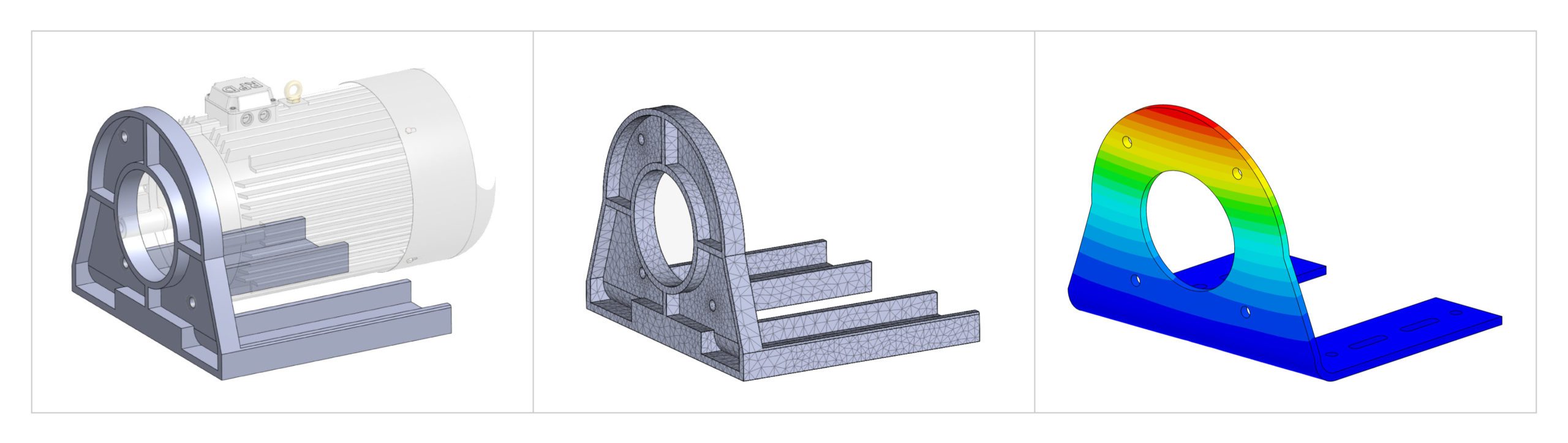
Simulation set up & mesh for the support bracket – The bracket has a frequency analysis type selected in SimScale. The mesh is generated automatically with 23.5K cells and the element sizing is set to automatic which takes the geometry fineness into account when deciding size. In this case, a moderately fine mesh has been chosen (the user has manual control over mesh settings). A point mass boundary condition is applied to represent the mass/moments of inertia of the whole motor eliminating the need to include the fully detailed motor geometry in the simulation. Our goal is to find the first eigenmode of the support bracket that needs the least energy and is thus the easiest mode to excite. An eigenfrequency plot is generated automatically.
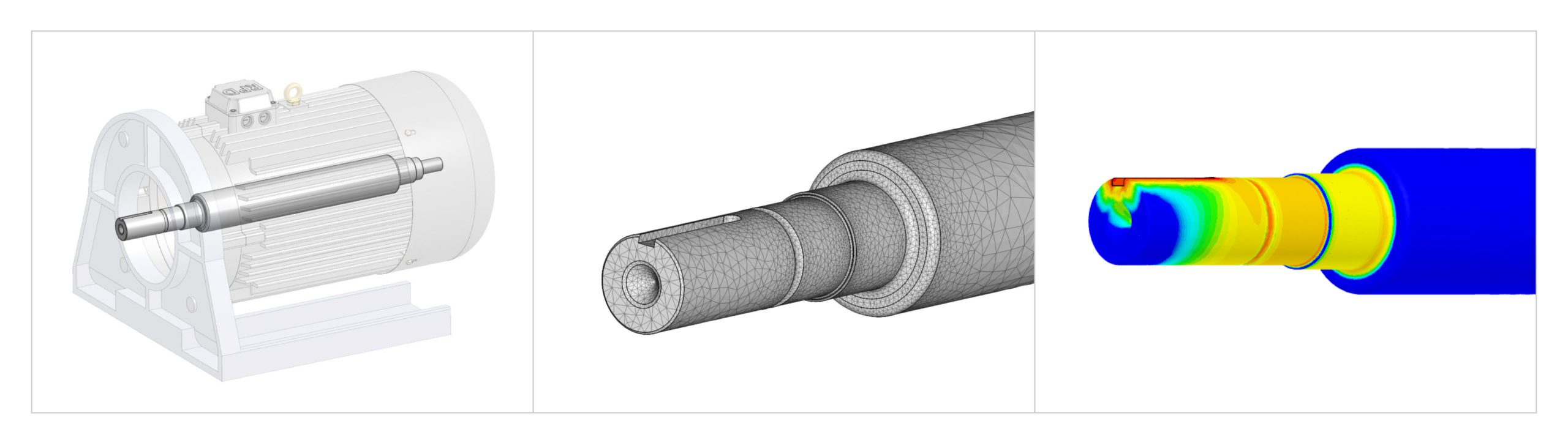
Simulation set up and mesh for the shaft – The motor shaft has a static (linear) analysis applied to it and from the materials library, we have selected mild steel as the primary material with linear elastic behavior. In a static analysis, we can define constraints and loads. The shaft has fixed support connected to the motor and the main shaft can be deformed due to remote load forces that represent applied torque using moments around the center of rotation. Deformable here means that the shaft is allowed to deform without applying additional stiffness. Undeformable would mean the shaft was a rigid entity which is not what we want. A centrifugal force is applied to the whole volume of the shaft and a rotational speed is set in radians/second. Automatic mesh settings are again used and a second-order tetrahedral mesh is generated for the shaft with 170K cells.
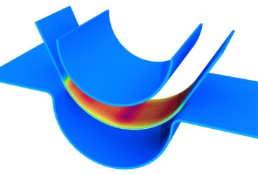
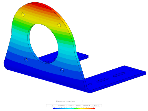
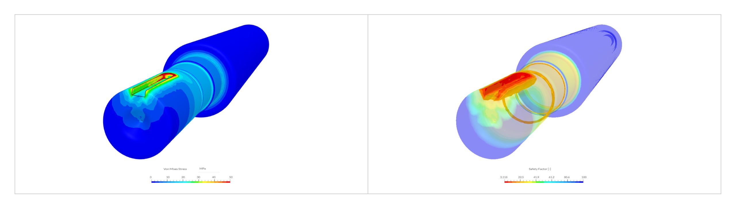
Post-processing – The SimScale platform’s field results allow us to visualize the deformed shape for each mode showing the displacement magnitude in meters. Statistical data is available to further interrogate the eigenmode number, eigenfrequency, Modal Effective Mass (MEM), Normalized Modal Effective Mass, and cumulative Normalized Modal Effective Mass (CNME). Multiple plots are pre-populated showing the eigenfrequency plot, modal effective mass, and accumulated normalized modal effective mass. From the static analysis, we can evaluate standard outputs such as Von Mises and Cauchy stresses, displacement, strain, and a new output variable that is the safety factor.
Design Insights
Bracket Vibration Analysis
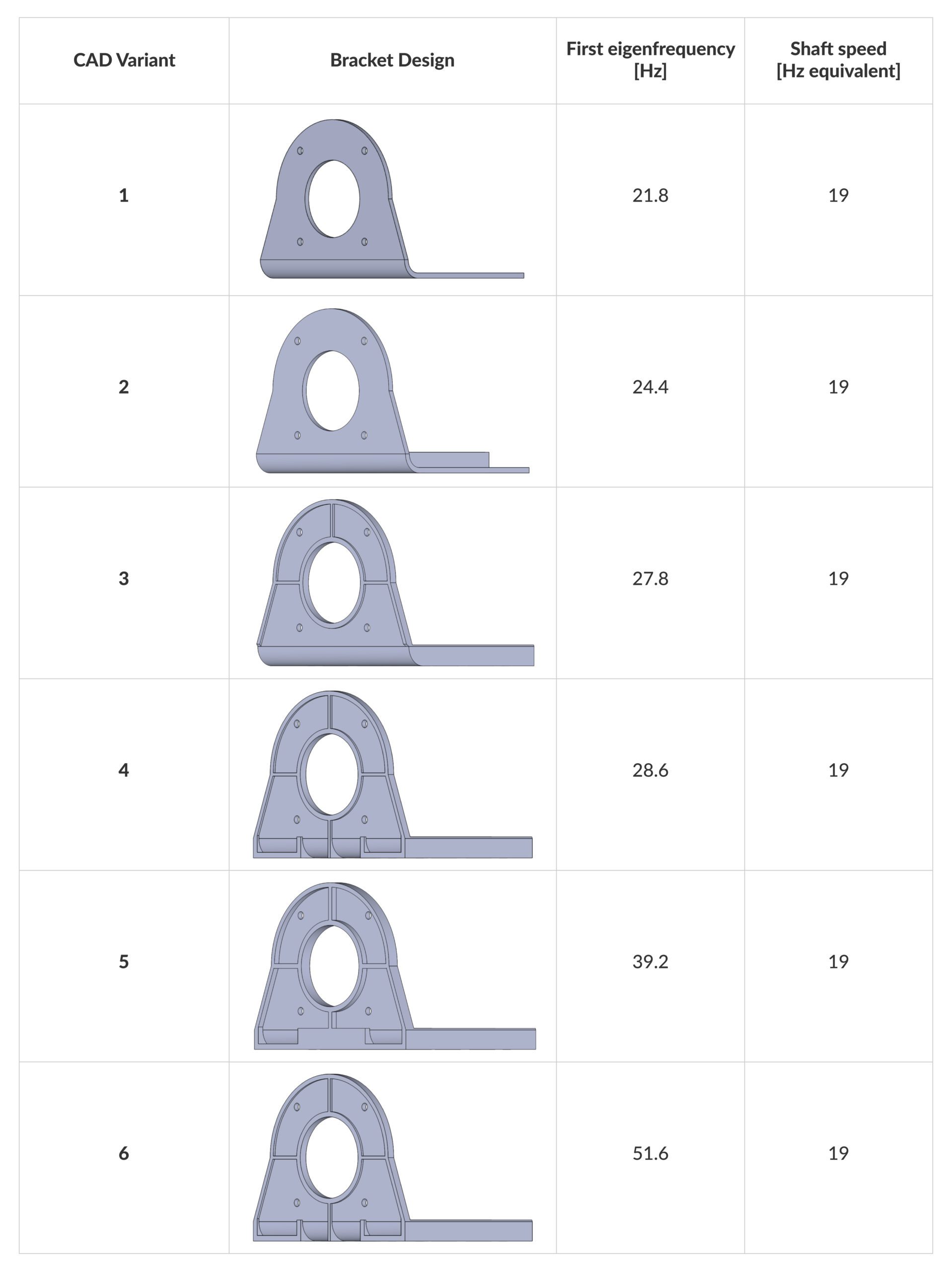
The support bracket vibration assessment shows us that the first eigenfrequency (21.8 Hz) of the original bracket (CAD 1) design is identified as being dangerous as it is too close to the shaft rotation speed equivalent in Hz (19 Hz), causing dangerous resonance effects and possibly leading to severe deformation. This could easily excite the first eigenmode just by running the motor and the excitation could cause resonance in the bracket itself —the displacement would move the motor beyond operating parameters and could cause damage. Although the first eigenmode is the most important to reconcile, different eigenmodes cause more displacement and deformation. They can all be visualized in SimScale. Geometry optimization by defining several CAD variants (1-6) of the support bracket can be simulated in parallel to achieve successful inflation of the first eigenfrequency value, away from the shaft speed. The full results are shown in the table below:
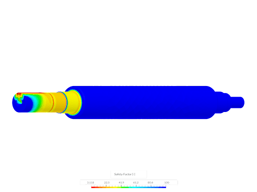
Shaft Safety Factor
The shaft structural integrity is simulated under real-world operating conditions, ensuring that the factor of safety did not drop below 2. Under two loading conditions with a nominal torque of 0.5 Nm and 10 Nm respectively we found the following:
- Load Case 1 – Nominal Torque of 0.5 Nm
- Results show a peak stress value 4.01 MPa.
- Results show a minimum factor of safety of 62.35, achieving the design goal.
- Load Case 2 – Maximum Torque of 10 Nm
- Results show a peak stress value 80.19 MPa.
- Results show a minimum factor of safety of 3.118, achieving the design goal.
Engineers must embed structural simulation in the cloud early in their product development processes to ensure that performance of critical design parameters is met using sound engineering analysis. Using parametric analysis, engineers can increase their confidence that the final product will operate and function within expected limits.