In general, human comfort in homes, offices, commercial spaces, theaters, and other buildings is one of the most important goals in building design and HVAC. Several studies have revealed that the proper placement and setting of room ventilation has a great effect on human cognitive performance and focus. Therefore, one of the current engineering challenges for building engineers is the adequate design of ventilation for maximum comfort.
What Are the Comfort Parameters?
Indoor air quality (IAQ) is a term that refers to the health and comfort of humans inside built environments. The air quality can be affected by different gases, particulates, electronic smog, dust, and other contaminants like mold or bacteria. The control of sources, filtration, and the use of ventilation are the primary methods for improving indoor air quality.
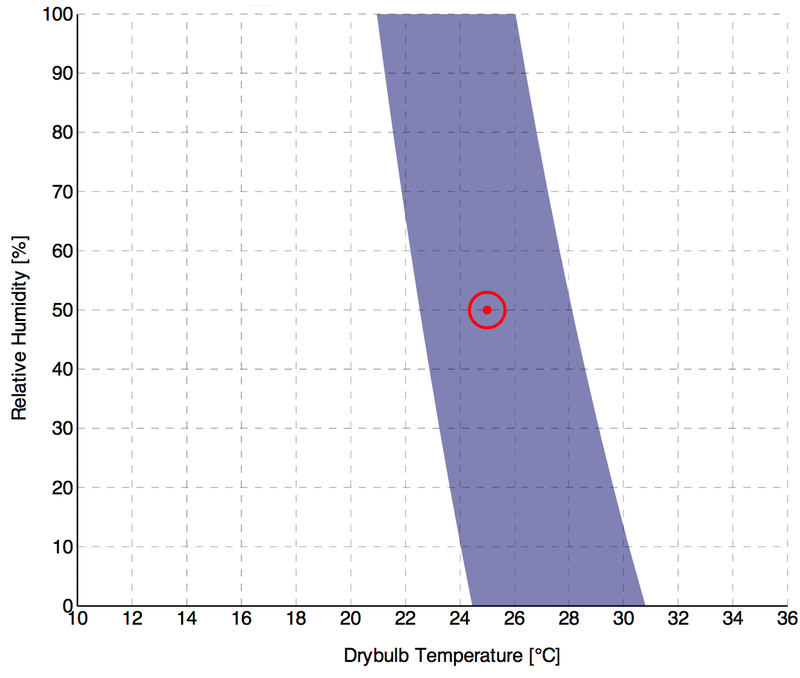
While indoor air quality plays is an important factor, the PMV/PPD model can better describe human comfort from an engineering point of view. This model was developed by P.O. Fanger, and uses heat-balance equations and empirical measurements about occupant skin temperature. Fanger’s equations are used to calculate the predicted mean vote (PMV) for the combination of:
- air temperature
- mean radiant temperature
- relative humidity
- airspeed
- metabolic rate
- clothing insulation [1]
ASHRAE Standard 55-2010 prescribes the requirements for indoor thermal comfort based on the PMV method. According to this method, at least 80% of the occupants have to be satisfied.
This free infographic illustrates how architects and engineers can use CFD to virtually test and optimize building designs and HVAC systems. Download it for free.

What Ventilation Rate to Use?
ASHRAE recommends a space-by-space ventilation rate, which is decided by a group of industry experts on a consensus basis. The ASHRAE 62.1 standard prescribes rates for non-residential spaces, while ASHRAE 62.2 is used for residences.
Occupant-based Ventilation Rates [3]
| IP Units | SI Units | Category | Examples |
|---|---|---|---|
| 0 cfm/person | 0 L/s/person | Spaces where ventilation requirements are primarily associated with building elements, not occupants | Storage rooms, warehouses |
| 5 cfm/person | 2.5 L/s/person | Spaces occupied by adults, engaged in low levels of activity | Office space |
| 7.5 cfm/person | 3.5 L/s/person | Spaces where occupants are engaged in higher levels of activity, but not strenuous, or activities generating more contaminants | Retail spaces, lobbies |
| 10 cfm/person | 5 L/s/person | Spaces where occupants are engaged in a more strenuous activity, but not exercise, or activities generating more contaminants | Classrooms, school settings |
| 20 cfm/person | 10 L/s/person | Spaces where occupants are engaged in exercise, or activities generating many contaminants | Dance floors, exercise rooms |
Area-based Ventilation Rates [3]
| IP Units | SI Units | Category | Examples |
|---|---|---|---|
| 0.06 cfm/ft2 | 0.30 L/s/m2 | Spaces where space contamination is normal or similar to an office environment | Conference rooms, lobbies |
| 0.12 cfm/ft2 | 0.60 L/s/m2 | Spaces where space contamination is significantly higher than an office environment | Classrooms, museums |
| 0.18 cfm/ft2 | 0.90 L/s/m2 | Spaces where space contamination is even higher than the previous category | Laboratories, art classrooms |
| 0.30 cfm/ft2 | 1.5 L/s/m2 | Specific spaces in sports or entertainment where contaminants are released | Sports, entertainment |
| 0.48 cfm/ft2 | 2.4 L/s/m2 | Reserved for indoor swimming areas, where chemical concentrations are high | Indoor swimming areas |
Where to Put the Ventilation for Maximum Comfort
When building engineers evaluate how to improve or maximize human comfort in a room, they usually consider two strategies:
Natural Ventilation
Efficient room ventilation can be achieved by using natural forces at almost no cost. Factors to consider are the effect of the outside wind, the pressure difference in the building, and stack ventilation (effect of buoyancy). The proper placement of windows and ducts is important, but this is relatively limited due to other design constraints. Therefore, building engineers have more possibilities to improve ventilation for maximum comfort when using mechanical solutions.
Mechanical Ventilation
This is the point where engineering simulation can play a significant role in the design process, especially for identifying the right location for ventilation to ensure maximum comfort. After determining the ventilation rate from the above tables, as well as the target temperatures and humidity, it is important to place the inlets in locations that will be least disturbing for occupants.
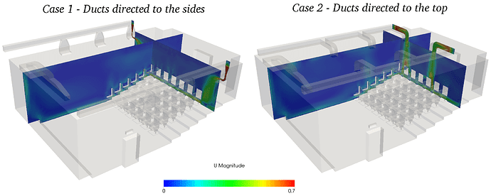
Take a look at this CFD project performed with SimScale, in which an engineer investigated the positioning of a duct in order to improve the ventilation system of a theater. Two different configurations of the inlet duct were virtually tested with a CFD analysis and the best version for thermal comfort was chosen. Mechanical ventilation simulation with SimScale cuts design time and improves validation.
If you want to try engineering simulation and investigate different placements of ducts, fans, and HVAC systems in buildings, then sign up for a free account here. All you need is a computer and Internet connection to get started with SimScale.
For more information on natural and mechanical ventilation simulation, check out this blog.
Download this case study for free to learn how the SimScale CFD platform was used to investigate a ducting system and optimize its performance.

References
- Fanger, P Ole (1970). Thermal Comfort: Analysis and applications in environmental engineering. McGraw-Hill
- https://en.wikipedia.org/wiki/Thermal_comfort#/media/File:Temperature-relative_humidity_chart_-_PMV_method.png
- https://en.wikipedia.org/wiki/Ventilation_(architecture)


