As a cloud-native application, SimScale is able to continuously release new features, and perform regular product maintenance on the fly. We realize that it’s often difficult to keep up with the latest news so we periodically group new features from the past quarter into a product update webinar, and this blog showcases all of the main new features released in Q2 2022. Enjoy!
Immersed Boundary Method (Beta)
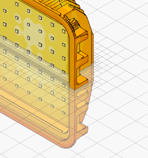
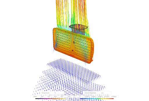
The Immersed Boundary Method (IBM) represents a major new Beta feature release allowing engineers to solve the most challenging thermal simulations faster and more robustly. This capability has been developed on top of our existing finite volume solver for conjugate heat transfer analysis type that solves for conduction, convection, and radiation heat transfer between solid and fluid domains.
The SimScale IBM solution uses a cartesian grid that the fluid and solid geometry get immersed into. The mesh generation is much faster and much more efficient in terms of cell count and solution speed than a typical finite volume mesh/solver. The method does not require any CAD simplification even for very complex models and allows engineers to turn around complex thermal simulations in minutes instead of hours.
IBM Feature Summary
- Automatic, parallel generation of CAD-adapted mesh
- Same underlying finite volume solver as for body-fitted meshes
- Works for internal & external flow setups
- Applicable to any conjugate heat transfer application (examples are electronics, lighting luminaires, heat exchangers)
Use Case & Benefits
- Solves challenging electronics thermal management/electronics cooling applications
- Drastically accelerates CAD-to-Results time —enables more design iterations faster
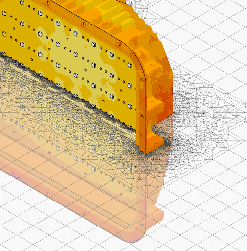
New Meshing & Result Controls
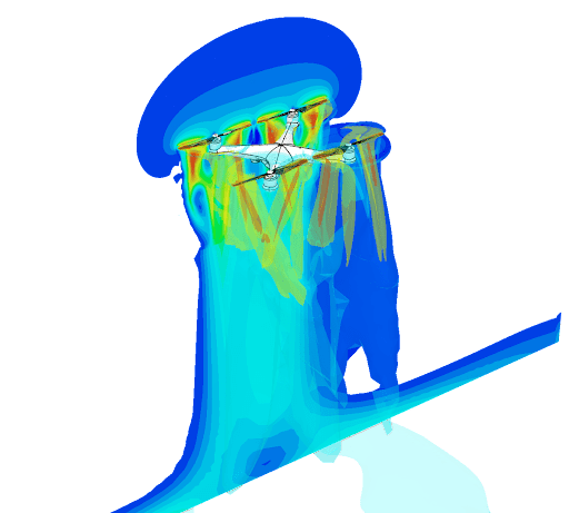
For the rotating machinery and flow control application area we have developed new mesh controls and results controls for the Multi-purpose Analysis type.
New Meshing Controls
For meshing, we now have the ability to control the mesh size locally. One or more mesh refinement zones are defined by geometry primitives that are created under the Mesh Setting > Refinement menu. A target cell size can then be defined for each primitive.
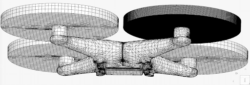
This new capability works seamlessly with our existing automatic global mesh generation and global refinement controls, the latter has also been improved. The net result is that users now have more efficient and robust meshing, plus very precise control over meshing in regions of interest, such as around rotors/impellers and small geometric features, which in turn results in a more accurate solution.
New Results Controls
For results controls, users can now monitor the Multi-purpose solver results in real time, enabling them to understand if the simulation is headed in the right direction and also get intermediate solutions for cases with longer run times.
Meshing & Results Controls Feature Summary
- Control over local mesh sizing is now also available in the Multi-purpose Analysis type
- All results quantities (3D + 2D) are now immediately available when computed in real time.
Use Case & Benefits
- Rotating Machinery and Flow Control
- Enables increased simulation accuracy while decreasing computational demand
- Monitor simulation results during runtime and react if needed
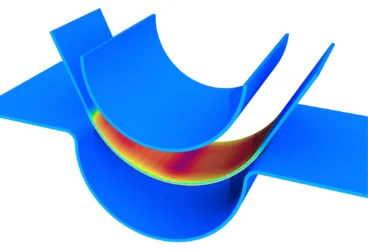
Simulating Cavitation
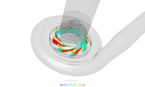
Another new feature for the rotating machinery and flow control application area is the Cavitation model for the Multi-purpose Analysis type.
Cavitation is the formation of bubbles in a liquid when local pressure falls below the liquid’s vapor pressure. When the pressure rises, these bubbles collapse and create localized shock waves. Cavitation can occur in pumps, hydraulic turbines, and marine propeller applications, and we should care about it because it can impact product performance (e.g. reduced flow rate), and usually causes damage/erosion to parts, plus generate noise and vibration.
SimScale uses the constant gas mass fraction model, and the cavitation results are available as total gas volume fraction, plotted as a 3D field variable. This enables users to easily predict and mitigate the risk of cavitation.
Cavitation Feature Summary
- Constant gas mass fraction model
- Results are shown in 3D as total gas volume fraction (Field variable).
Use Case & Benefits
- Applicable to turbomachinery and flow control
- Enables a more realistic simulation of fluid behavior
- Provides design insights to avoid/minimize cavitation
Atmospheric Boundary Layer Inlet Boundary Condition
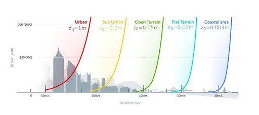
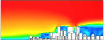
For Architecture, Engineering, and Construction (AEC) simulations relating to external wind prediction, building aerodynamics, and pedestrian wind comfort (PWC), we have introduced the ability to define an atmospheric boundary layer inlet boundary condition.
Users input three parameters (Reference Velocity, Reference Height, and Ground Roughness) and SimScale takes care of setting up the logarithmic boundary condition by automatically calculating the velocities and turbulence quantities. This provides a far more accurate representation of the atmospheric boundary layer, in turn resulting in simulations that closely match the real world.
Atmospheric Boundary Layer Inlet Boundary Condition Feature Summary
- New Boundary Condition —Atmospheric Boundary Layer Inlet
- Specify wind speed based on a logarithmic law, by defining reference height, reference speed, and ground roughness
Use Case & Benefits
- AEC / Aerodynamics
- Velocity and turbulence quantities are automatically defined
- Enables a more accurate representation of the atmospheric boundary layer
Optimized Surface Data Export
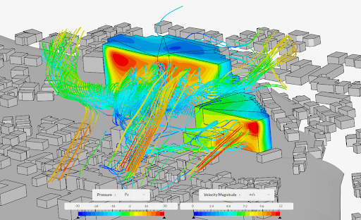
A second new feature for AEC applicable to incompressible Pacefish® Lattice Boltzman (LBM) solver and Pedestrian Wind Comfort (PWC) based simulations is the ability to optimize surface results data export to specific surfaces/regions. The LBM solver is a transient/unsteady flow solver which inherently results in large results datasets. Although such large datasets are typically not an issue for our cloud-native platform, there are cases where it is beneficial to reduce the dataset either for more efficient results visualization or for further downstream post-processing on a specific subset of the data.
Optimized Surface Data Export Feature Summary
- Statistical averaging —available for incompressible (LBM) or Pedestrian Wind Comfort (PWC) simulations
- Selecting the ‘surfaces of interest’ for which the results data should be exported
Use Case & Benefits
- Applicable to AEC / Pedestrian Wind Comfort (PWC)
- Reduces simulation runtime, lowering simulation cost
- Produces a more manageable results dataset
Base Excitation – Vibration Testing
In response to requests from our electronics industry customers, we have introduced a base excitation boundary condition for structural harmonic analysis. This new boundary condition allows users to define an excitation applied to a structure, defining the magnitude, direction, and phase angle of acceleration.
The Base Excitation acceleration magnitude can be specified either as a constant value or as a function of frequency using a table input. This allows evaluation of a structure’s response spectrum against a known acceleration spectrum such as industry-standard vibration/shaker table tests, or seismic loads.
Base Excitation Feature Summary
- New Boundary Condition: Base Excitation
- Specify direction, acceleration magnitude, and phase angle
Use Case & Benefits
- Relevant for engineers performing vibration testing, especially useful for electronics PCB and components testing
- Used to predict the stresses within the structure under external excitation
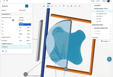
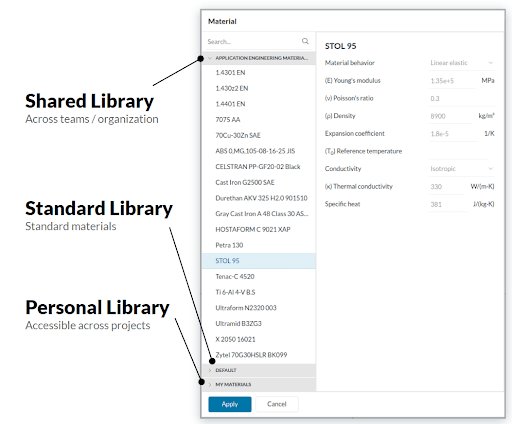
Personal & Shared Materials Data Management
There are two new important features released that provide the ability to manage materials and materials data in a better way across projects, and across users within an organization:
- Personal Materials Library: This allows individual users to import and define their own custom materials that can be managed for use across all of their projects.
- Company Materials Library: Available to SimScale Enterprise or Team accounts is the ability to define a set of materials centrally and then share it across all users in a team or organization. Organizations can now centrally control what materials engineers use in their simulations, ensuring consistency, and adherence to best materials practices. The materials data can be uploaded programmatically via the SimScale API, allowing companies to import and synchronize data from their own or preferred third-party material libraries.
Personal & Shared Material Libraries
- Personal Library: Users can create and save their own custom materials, for use in the same or other projects.
- Shared Library: Allows users and companies to create, save and maintain a custom set of materials via the SimScale API
- Shared Library: Upload supports JSON format.
Use Case & Benefits
- Ensure the use of consistent materials data across projects, users, and organizations.
- Avoids the manual, time-consuming, and error-prone process of copy-pasting material properties.
- Personal Library: Users can save time by creating a personal material database used across multiple projects, compared to editing and generating custom materials for each project as needed.
- Shared Library: Companies can save time by deploying material databases that are available to all users rather than each user creating custom materials. Avoids errors due to inconsistent material properties being used by different users in different teams or departments.
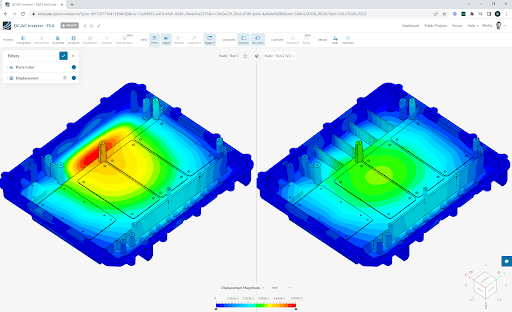
Side By Side Post Processing
SimScale has a fully integrated post-processor offering 3D visualization of the result fields, including 3D animations. The new Results Comparison View provides the ability to compare results from two different simulations side by side (from either the same camera angle, and same zoom level, or using a decoupled camera mode). This provides designers & engineers with the ability to quickly and clearly see before and after results from multiple design iterations.
Results Comparison View Summary
- Split screen comparison view, enabling ‘side by side’ design comparisons
- Cameras can be synchronized
Use Case & Benefits
- Two designs can simultaneously be investigated and differences understood, without having to cut and paste screenshots and struggle with matching camera views and/or scale differences.
Export Animated Results in MP4 Format
Highly requested from our enterprise customers, another new post-processing feature is the ability to export animated results in either gif or MP4 format. Prior to this users would have to have access to external screen capture video processing software, so this new feature makes this process far easier and faster for SimScale users.
GIF & MP4 Format Export Summary
- Native videos can now be exported in gif and MP4 formats.
Use Case & Benefits
- Eliminates the need to use a screen capture tool for videos.
- Allows to easily export and share animated results in standard format with simulation stakeholders.
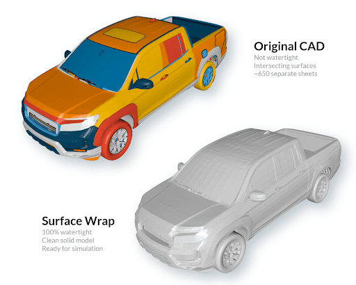
Surface Wrapping for Faster External Aerodynamics Simulations
In the real world, most simulation engineers often have to deal with geometry that isn’t well prepared for simulation. Examples are missing facets, self-intersecting surfaces, and holes where there shouldn’t be any. Cleaning up complex CAD geometry can be an onerous task and can take hours of work that could otherwise be applied to more productive simulations! Surface Wrapping is a new pre-processing feature that makes simulation more accessible by taking away the need to clean up CAD geometry. Surface Wrapping was developed specifically for external aerodynamics applications, such as CFD simulations on cars, aircraft, or building aerodynamics, really any aerodynamics application where the CAD model may have excessive detail that is not important for the simulation. It can wrap and “seal” a complex surface CAD model in seconds, saving considerable geometry preparation time. The resultant geometry is watertight and a real CAD entity that is ready for simulation.
Surface Wrapping Summary
- New CAD operation creating a watertight clean solid from any underlying geometry
- Fully automatic with optional parameters to adjust fineness etc.
Use Case & Benefits
- Vehicle / Building Aerodynamics
- Reduces manual CAD preparation time
- Enables the simulation of a certain class of models that could not be simulated otherwise (e.g. scanned models, bad surface models, etc.)
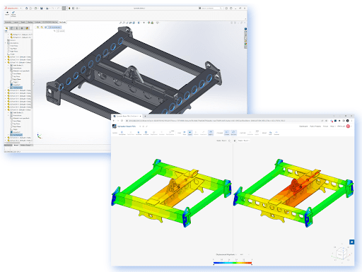
Associative CAD Geometry Import
CAD associativity is a major new workflow enhancement for SimScale that makes it really easy for users to quickly simulate different design iterations imported from their CAD system. Once a user has imported a CAD model and has set up their simulation, this new feature then allows the user to select a different design iteration of the model from their CAD system and swap it with the initial model in SimScale, retaining the simulation setup. This saves considerable simulation setup time. This CAD associativity capability is currently available for Onshape® and also with Solidworks using the SimScale Solidworks® Plugin for associative CAD import.
Associative CAD Geometry Import Summary
- CAD Associativity for Onshape®
- Solidworks® Plugin for associative CAD import
- Allows geometry to be swapped retaining load and boundary condition assignments
Use Case & Benefits
- Both OnShape and Solidworks users can directly import models without having to export and then import them into SimScale resulting in a more convenient data transfer.
- Saves time and allows users to rapidly explore multiple CAD designs without having to remap simulation assignments.
Calculate New Result Fields Based on Existing Fields
The new results field calculator is a new post-processing feature that allows users to calculate new results fields from any pre-existing results fields. Users can now develop customized results plots to meet their specific needs without having to leverage external post-processing tools. Any existing result fields can be used in the definition of the new field, so you can use other derived results fields to build up more complex expressions.
Results Fields Calculator Summary
- Calculate derivative scalar and vector fields on the fly with mathematical operators
- Any existing result fields can be used in the definition of the new field
Use Case & Benefit
- General —all simulation types
- Customize your results in the post processor to visualize your specific needs
- Avoids the need to export results to external post-processing tools or spreadsheets
Take These New Features for a Spin Yourself
All of these new features are now live, in production on Simscale, they are really just one browser window away from you! If you wish to try out these new features for yourself and don’t already have a SimScale account then you can easily sign up here for a SimScale trial.
Follow along yourself in our on-demand webinar where our experts discuss and demonstrate these new features, highlighting their application, and benefits: