New to engineering simulation or to SimScale? Then meshing might be one of the things you’re struggling to learn. This article aims to teach you a few tips for meshing your CAD model and ensuring accurate results of your structural analysis.
Mesh generation (also commonly known as grid generation) is the practice of generating a polygonal or polyhedral mesh that approximates a geometric domain. Three-dimensional meshes are required in physical simulations such as finite element analysis (FEA) or computational fluid dynamics (CFD) and need to consist of tetrahedra, pyramids, prisms, or hexahedra.
At present, SimScale allows the meshing of structures with tetrahedral meshing.
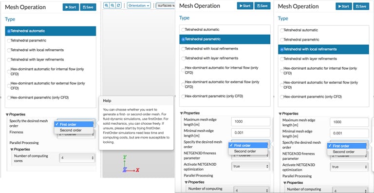
As shown in Fig. 01 below, all these cases allow for the specification of mesh order—either first or second. Using a first-order generates a mesh with four-noded tetrahedral elements, while a second-order creates a mesh with ten-noded tetrahedral elements.
A general overview is available in the SimScale documentation. In this article, we will discuss some important points to remember when considering problems related to solid and structural mechanics. Most of the aspects discussed here are pertinent to both tetrahedral and hexahedral elements, but the discussion is primarily focused on the tetrahedral mesh.
The purpose of a helmet is to protect the person who wears it from a head injury during impact. In this project, the impact of a human skull with and without a helmet was simulated with a nonlinear dynamic analysis. Download this case study for free.

Meshing How to Mesh Solid Bodies for Structural Analysis: Identify Symmetry
In many problems, it can be helpful to identify some of the symmetries that can exist in geometries. Using symmetry is one of the common and powerful ways to reduce the size of the problem. By definition, symmetry exists if there is a symmetry of geometry, loads, and constraints about a line or plane of symmetry.
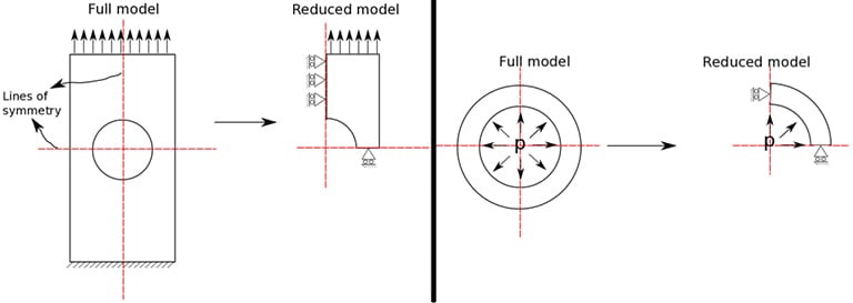
As shown in Fig. 02, the symmetry of the object is exploited to create a reduced model for computation. Nodes are placed along the lines (in 2D) and planes (in 3D) of symmetry. These nodes placed along the lines/planes of symmetries are constrained for displacement perpendicular to these lines/surfaces and rotations along the line/surfaces. Considering just a quarter of the CAD model allows for >75% reduction in the computational effort and time!
Tip 01: Does the CAD model being meshed have any symmetry? The symmetry could be along a plane or could be along an axis.
Meshing Considerations Interfaces and Boundaries
Structures could have interfaces and boundaries, such as interfaces between multiple materials, contact, cracks, etc. Mathematically, the FEM is based on the assumption that the displacements are continuous inside an element. Interfaces are regions where possible discontinuities, like cracks, could occur. This means the displacement needs not be continuous. Irrespective of a jump in displacements, there is a definite jump in the stresses at an interface.
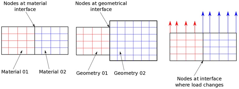
For example, consider the material interface shown in Fig. 03. Here, each material has a different modulus. In the absence of cracks, the strains at the common nodes are same. Now, knowing that stress = modulus x strain leads to different stresses on each side of the interface. In other words, we have a jump in stresses. Such a jump cannot be captured by an element across which an interface passes. Similarly, other conditions where there cannot be an element across a boundary include:
- When geometry changes, elements cannot cross these boundaries, and it is necessary to have nodes at the interface
- When loads change abruptly, nodes need to be present at the interface where the load suddenly changes
- Nodes need to be present at points where concentrated loads are applied
Automatic meshing algorithms consider the interfaces as long as the CAD model is partitioned along the interfaces. In general, the automatic tetrahedral mesh works well, but if an element is overlapping across an interface, then partitioning becomes necessary.
Tip 02: An interface can never pass through an element!
Meshing Mesh Refinement and the CAD Model
The automatic mesh generators generally start by creating a surface mesh of triangles. They further extrapolate by using these triangles to form tetrahedrons in the volume. In many cases, the shape of tetrahedrons formed inside the volume can get quite distorted, leading to failure of the mesh generation. This is generally encountered in two cases:
- Complicated CAD geometries
- Geometries with high-aspect ratios
Depending on the geometry of the structure, the CAD model could contain geometries of high aspect ratios, fillets, etc. In such a situation, it is possible that the ad hoc automatic meshing might not generate the best meshes. Most often, these small structures are meshed over when large elements are used, and often the mesh does not conform to the exact geometry. In such cases, it is best to resort to a priori mesh refinements.

Fig. 04 demonstrates the ability of SimScale to provide an excellent mesh refinement. The areas of the CAd model that need refinement can be clearly identified, and the mesh generator ensures a suitable mesh with refinements.
Tip 03: Mesh refinement for the CAD model is a definite necessity if the structure deals with parts of significantly different dimensions.
Meshing Problems Meshing for Nonlinear Elasticity: Contact Problems
Problems involving linear elasticity is one of the well-researched problems in mechanical engineering. For all linear elasticity problems, irrespective of mesh sizes, the Newton-Raphson iteration will converge in one iteration. However, it is always recommended to perform a mesh refinement and convergence study to ensure the accuracy of the solution. However, the same cannot be said when a material nonlinearity (like hyperelasticity, viscoelasticity, and plasticity) is involved. The problem can be well-posed and a unique solution could exist. However, the problem might fail to converge if the mesh is not sufficiently fine in regions where the strong nonlinearity is observed. Here we have provided some tips with regard to contact problems which are highly nonlinear in nature.
Contact is highly nonlinear in nature and to this day remains a computational challenge for modeling large deformation contact problems. Thinking of it in simple terms, at a certain time there is no contact and then suddenly there could be contact. Most problems involving hyperelasticity are nonlinear but continuous. However, it must be remembered that contact is a switch or a discontinuity.
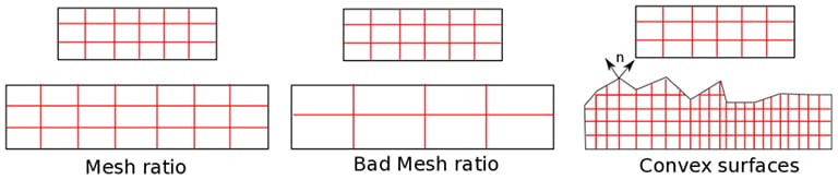
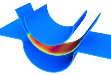
As shown in Fig. 05, meshing can significantly improve solutions for structural analysis problems involving contact. SimScale currently allows contact where the sliding displacements are small. For such problems, the mesh ratio between master and slave surfaces must be optimal. A general rule of thumb is that, at worst, one master element should be less than 2-3 slave elements. Additionally, if one or more surfaces are convex in nature, i.e., has sharp corners, then it can lead to non-uniqueness of solutions. The normal and tangential vectors are needed to calculate the distance between the two surfaces along the direction of these vectors. If a sharp point exists where two normals can be defined, this leads to ambiguity in choosing the normal vector causing a non-uniqueness.
Tip 04: The mesh ratio between master and slave surface needs to be optimal. Avoid sharp corners in contact surfaces!
Meshing Problems Identify Stress Singularities and Concentrations
Have you ever wondered why airplane windows are not exactly rectangular but are curved? Some of the first airplanes had rectangular windows, but it was quickly discovered that the sharp corners lead to stress concentration and crack initiation. Identifying such singular points and refining the mesh in these areas can lead to more accurate results of the structural analysis.
Firstly, what is a stress singularity? A stress singularity is that point in a mesh where the stresses do not converge. Theoretically, the stress at this point is infinity, and as the mesh is being refined, the stress at this point continues to increase. Nevertheless, it is very important to note that the displacements calculated at these stress singularities remain accurate even though the actual stress at the point remains questionable. That aside, at a very small distance from the point, the stresses calculated are accurate.
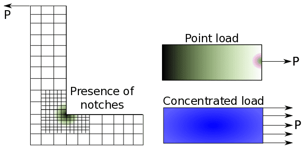
However, such occurrences are very common in reality, and the user needs to identify these areas. They are regularly encountered at points where a point load is applied, where there is a presence of sharp corners, and at points with restrained boundary conditions over a single point, as shown in Fig. 06. Such occurrences are often seen in welded parts, for example.
It is important to answer the question whether the local phenomenon is of interest. If yes, then the easiest solution is to refine the mesh near the singularity. If no, a coarse mesh could do the job. Due to the applicability of the St. Venant Principle, the local stress singularity is lost as one moves away from the point. Thus, the bulk results obtained are still accurate.
Tip 05: Are there singular points? Both mesh refinement and a coarse mesh are possible ways depending on the quantity of interest.

Meshing Locking Effects in Bending Problems
Geometric nonlinearities and locking effects are commonly observed when solid elements are used for meshing thin structures. This is especially true if they are subjected to bending loads. This kind of locking is known as “shear locking”. Shear locking should not be confused with the membrane or volumetric locking effects. Shear locking is observed since the first-order elements using linear interpolation function for displacement. In other words, displacements are represented by a linear function and the derivative of a linear function is constant. Thus, the strains are constant throughout an element. In reality, this is not the case. Such an incorrect estimation of strain inevitably results in an inaccurate estimation of the strain energy, and the overall structure exhibits a much larger stiffness. The net displacement of a structure will be much lower than that observed in the actual structure.
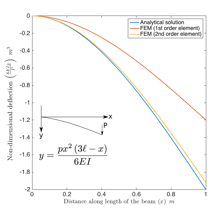
As shown in Fig. 07, a simple cantilever beam is considered, for which an exact analytical solution exists. The displacement of the beam is plotted as a function of its length. As evident from the graph, second-order elements perform very well, predicting a solution to acceptable standards of errors. In contrast, using first-order elements leads to a complete under-prediction of the tip displacement.
There are two possible solutions to circumvent this problem:
- Mesh refinement along the thickness by using multiple elements (at least 5+)
- Using a second-order mesh could significantly reduce the locking effect
The downside of the first approach is that it increases the number of elements and significantly increases the computational size. For example, the beam is 1000 mm in length, 250 mm in breadth, and 10 mm in thickness; if we had only one element along the thickness, we are looking at approximately 2500 elements. By refining using the first criterion, the elements left are of a size of around 2 mm, meaning there are about 312,500 elements. Alternatively, by using the higher-order element, the 2,500 second-order elements could already solve most of the problem.
Tip 06: If you are dealing with thin structures or with mostly bending problems, a second-order mesh is a definite yes!
Meshing Locking Effects Due to Incompressibility
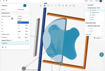
Yes, again! Volumetric locking is commonly observed due to incompressibility constraints. This type of locking is known to occur in rubbery materials. It is also important to note that plasticity is a perfect example of incompressibility. Volumetric locking is addressed in sufficient detail in the SimScale blog article on modeling elastomeric materials.
Tip 07: Volumetric locking also needs to be considered for plasticity!
The overall tips on meshing your CAD model discussed here are not a comprehensive list of things to do, but rather provide a general idea of the minimum things to account for while using FEM for structural analysis problems.
Learn how to get easy access to cloud-based tools for CAD and simulation by watching the recording of the webinar “How to Optimize Medical Devices with Cloud-Based Simulation” in partnership with Onshape. All you need to do is fill out this short form and it will play automatically.
Alternatively, watch the recording of our “More Durable Consumer Products with FEA” webinar. Just fill out this short form.