Due to the large number of students using SimScale, I thought it would be interesting to start a series of simple simulations focused on the principles of aerodynamics. In this post, I will introduce the ground effect, which occurs during the take-off and landing of airplanes.
What is the Ground Effect?
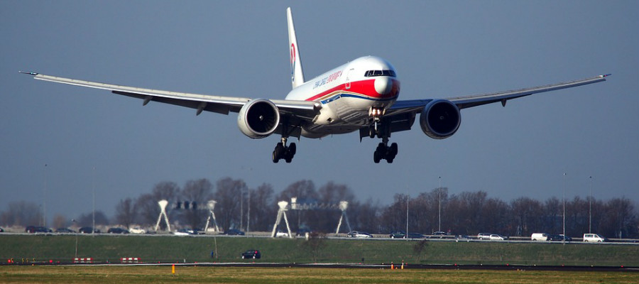
When talking about aircraft, the ground effect is the increased lift and decreased aerodynamic drag that the wings generate when they are close to a fixed surface, such as the ground. This can give the pilot and passengers the sensation of the aircraft floating during landing [1].
Geometry
The very basic nomenclature related to an airfoil shape is presented in Figure 1.
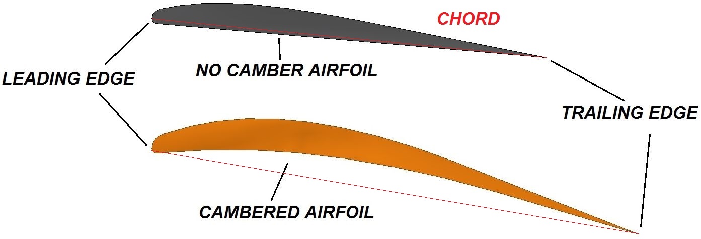
As you can see, the wing shape that we will be using in the analysis (without camber), looks quite nice. It’s not perfect, but the spline of the upper surface is tangent to the leading edge curve and forms a smooth shape. The wing’s span (the domain width) is 0.1 [m] because I wanted to avoid a pseudo-2D case. The wing’s angle of attack was set at 5 degrees.
Setting Up the Simulation
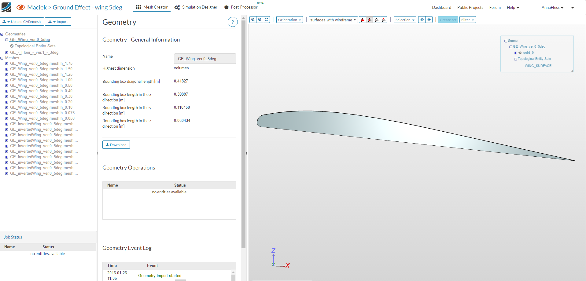
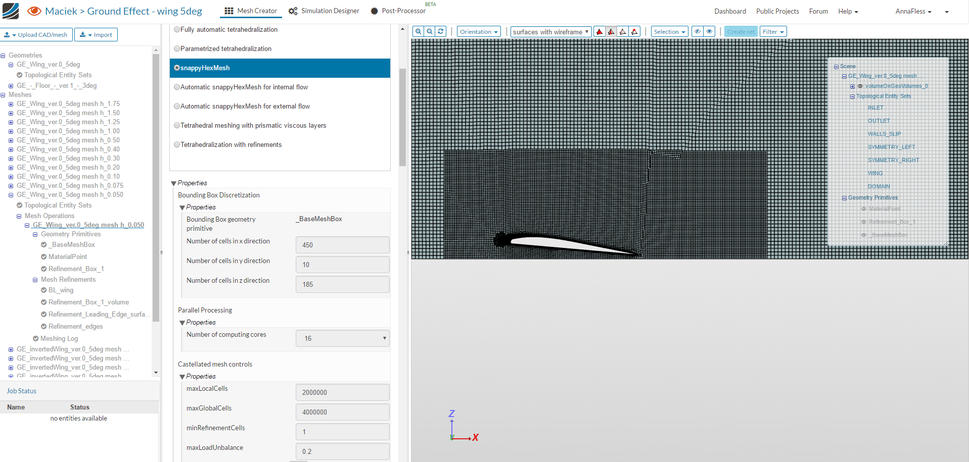
To set up the ground effect simulation in SimScale, I first uploaded the CAD model of the classic wing, which was set at a 5-degree angle.
I then used the manual snappyHexMesh to mesh the domain using a Base Mesh Box, a smaller Cartesian box near the wing, and four meshing refinements:
- Layer refinement applied to the surface of the wing
- Region refinement applied to the smaller Cartesian box
- Surface refinement on the leading edge of the wing
- Feature refinement on the edges
The incompressible fluid flow simulation was set up using the Simulation Designer tab with a k-omega SST turbulence model, steady-state behavior and the SIMPLE solver.
An inlet velocity of 40 m/s and a pressure outlet of zero was assumed for the boundary parameters. The same was done for an inverted wing.
Domain Size Check
I’d like to mention one very important aspect in relation to all CFD analyses, which is simulation domain size. Despite fluid flow simulations becoming increasingly popular and robust, many engineers keep making the same mistake: running their simulations in domains that are too small. I have presented my method of domain-size check via velocity values at the domain’s boundaries below.
This case is very simple—a single geometry object, and all I needed to do was to check the velocity in three points:
- at the inlet
- at the top
- at the bottom
The picture below presents upper and lower boundary points. I deliberately chose the maximum and close to the minimum region.
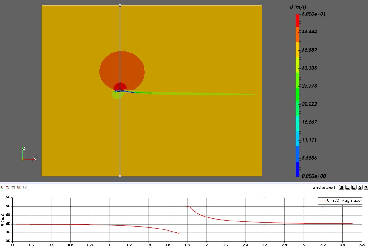
Predicted velocity differences:
at the bottom: v=39.895 [m/s] and it gives -0.26%.
at the top: v=40.255 [m/s] and it gives +0.64%.
*Note: The flow velocity was set at 40 [m/s], thus the selected starting domain size was sufficient.
Results
That’s it in terms of basic information. Now, let’s take a look at the results.
As you can see in the picture above, I started my investigation from the point where there was no influence of upper and lower wall. I then I gradually decreased the space between the wing and the wall. I’ve analyzed two situations:
- standard, classic wing where lift was generated (bottom wall was moved up)
- inverted wing where downforce was generated (top wall was moved down). In this case, I described the downforce as the negative lift (hence “–L” in the notations) to avoid misunderstandings with drag.
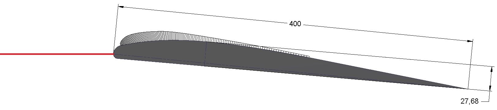
The “height” in this virtual experiment was measured from the red line. Consequently, the values in meshes/cases and table’s descriptions don’t reflect the exact distance between our wing and virtual wall. I simply needed a constant starting point, and this approach made the process easier.
Also, to be able to draw some general conclusion, I plotted particular curves in function of height (h) to chord (c) ratio. Chord length was 0.4 [m] and is presented in the picture showing the airfoil shape.
So, what do we have here? First and foremost, the wall influence is clearly visible from the start. This is very important to remember for all beginners–once more, domain size! Secondly, the classic and inverted wing differ from each other.
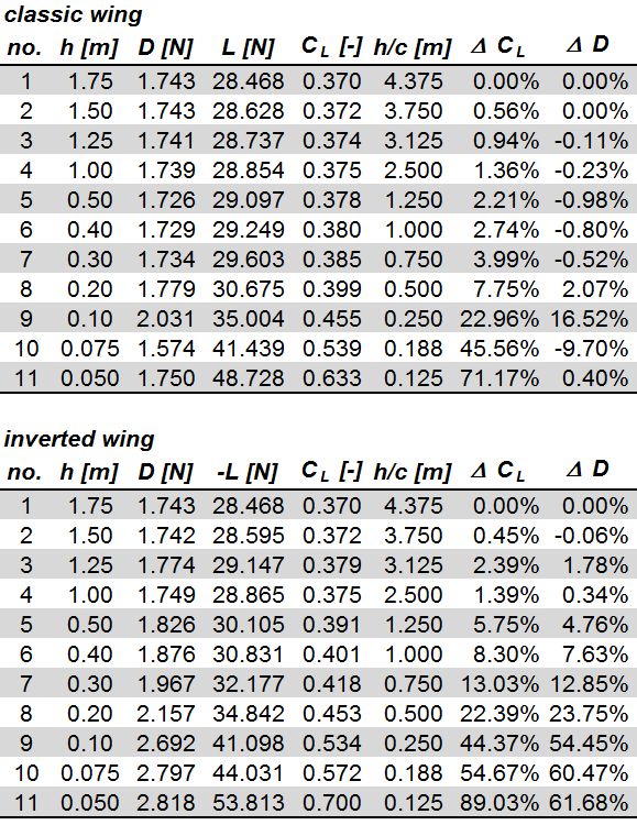
In the results, I’ve included the pressure forces only. The viscous ones, because of their very low values, were ignored.
Tables with outcomes:
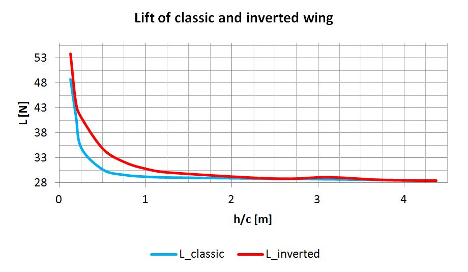
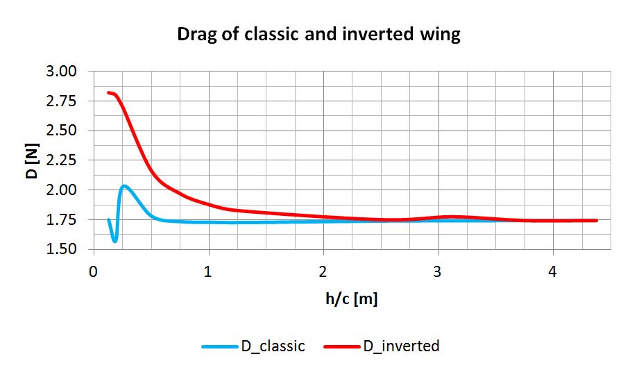
Plots:
Conclusions
Standard wing
The lift coefficient increases very gradually as we get close to 1:1 mark of h/c ratio. If we add some accuracy margin to our simulation, we can even assume it is stable until this point. Then, suddenly, it speeds up and reaches over 70% of the reference coefficient value. This means we can extract up to about 70% more lift from this particular wing, just by limiting the space below. Another important factor to consider is that, at the same time, the wing’s drag stays at the same level. Of course, there are some fluctuations at one point, but it doesn’t seem to be significant in comparison to the overall gains in lift force.
Inverted wing
Here the situation looks a bit different. The lift coefficient (and lift force) increases slightly faster. However, it’s compromised by the considerable rise in drag. The good news is that it’s still positive as the net percentage value is just below 30% for the smallest gap.
Discover all the simulation features provided by SimScale. Download the document below.

References
- Ground Effect – https://en.wikipedia.org/wiki/Ground_effect_(aerodynamics)


