As the world’s population continues to grow, energy demands are also rising. For some time now, most of the common devices in our homes, workplaces, and even social lives rely on power to function. Developing countries are also relying on heavy industries much more in a bid to boost prosperity. The trending topic, however, is climate change and renewables. Sources of clean energy can be harnessed to ensure the population has the power it needs to sustain its way of living without using up vital resources. But how exactly is this power generated?
To generate renewable power, natural resources such as wind, solar, hydro, and potential energy are used. Generally, the natural movement of air or water resources like rivers and high wind regions are converted into electrical energy by means of a mechanical body that induces an electromotive force (EMF)—except for chemical or solar, for which energy is harnessed in other ways.
Most industrial applications, such as steam turbines, nuclear plants, and wind turbines, rely on this type of conversion. Just as there has been a race for electric vehicles in a bid to reduce the population’s reliance on environmentally damaging fossil fuels, demands are increasing for cleaner methods of power generation. While the current global primary source of energy is coal, (nearly 40%) compared to approximately 6% of renewable energy, more nations are looking for renewable resources to replace it.
In this study, we focus on one greener method that accounts for around 16% of world power generation: hydropower. Harnessing power from water sources is made possible by water turbines and pumps such as centrifugal pumps and their impeller pump components. Here we offer an introductory understanding of turbines and pumps in turbomachinery applications.
Water Turbine Design Types
There are three types of water turbines which you can find more information on in this overview of turbine design types. The three types are:
- Impulse turbines, including Pelton, Turgo, and cross-flow turbines
- Reaction turbines, including propeller turbines, Kaplan turbines, and Francis turbines
- Gravity turbines, including overshot water wheels and the Archimedes Screw, which is a pump often used as a reverse turbine
With impulse turbines, jets of fluid strike a set of curved blades that change its velocity’s direction and exchange momentum; this applies a force on the blades creating a torque that allows the blades to rotate. The rotation then generates an EMF due to electromagnetic induction.
In comparison, a reaction turbine is driven by the change of fluid pressure while striking the propellers or the blades of a submerged turbine. Pressure drop inside the turbine converts the existing potential energy into kinetic energy driving the turbine propellers. Turbines in this category require a casing to maintain the fluid pressures continuously.
While sharing similar turbomachinery mechanisms, turbines work to decrease energy in a system while pumps aim to increase the energy of the fluid stream. In order to explain how pumps work, let’s focus on a very popular pump design; the centrifugal pump.
The Centrifugal Pump: A Popular Impeller Pump Choice
Generally, industries rely on a centrifugal pump for applications including pumping sewage, processing food, or treating water. In fact, nearly 85% of pumps produced today are centrifugal pumps. This is probably due to their multiple capabilities and ease of scaling up for larger applications.
Depending on what fluid it will be handling, whether low flow rates are present and therefore need increased pressure, and in what orientation it will be installed, a centrifugal pump can easily be adapted. This has led to many additional sub-types of centrifugal pumps gaining their own name. Their size and designs may vary depending on the application they are being used for, but their working mechanism remains the same.
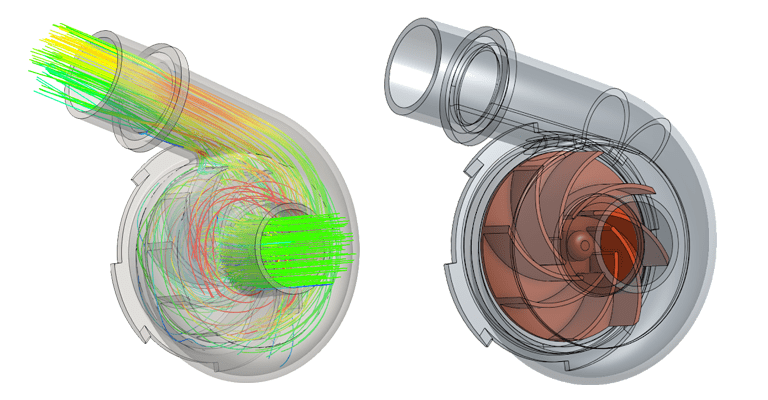
This type of pump converts rotational energy, such as from a motor, into energy in a fluid. Its two most important components are the pump impeller inside, a rotating element with multiple blades, and the outer casing, which ensures no pressure is lost. Water enters a centrifugal pump axially through an eye in the casing and hits the blades of a pump impeller inside.
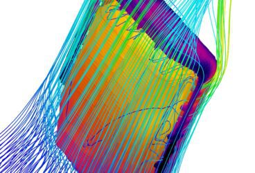
For a centrifugal pump to work at its best, a lot of design changes and tests are needed. Optimizing the design physically would require a lot of manpower and time. To cut down this cost in the design phase, we would need a virtual testing tool which allows us to make modifications quickly and reliably. CFD gives us this advantage.
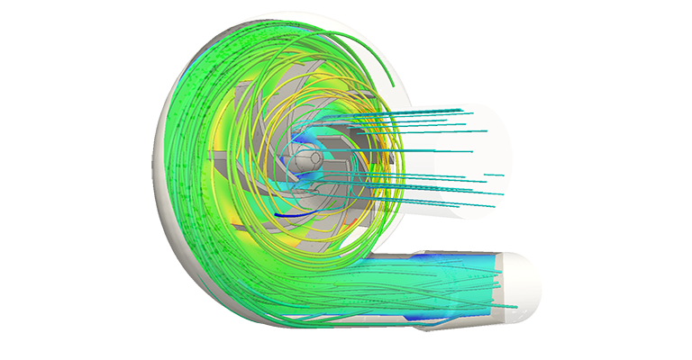
A CFD analysis can help predict and visualize the fluid (water) flow inside a pump and also gives us insights into where we can optimize the design, even before the production of the pump itself. In the next section, we discuss how CFD can be used to optimize an impeller of a pump.
How Does an Impeller Pump Work?
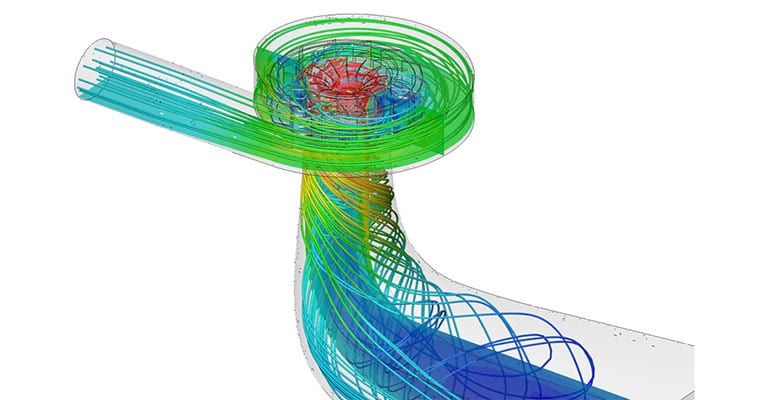
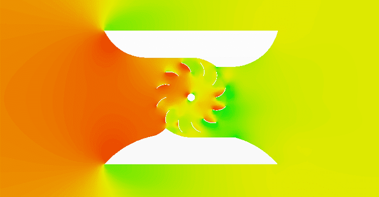
The key component of a centrifugal pump is its impeller, as it transfers energy from the pump motor to the fluid. An impeller pump relies on inertia, the natural tendency of an object or fluid to move in a straight line when moving in a circular motion. Water hitting the blades of the impeller naturally moves outward in a direction that is tangent to the radius. This creates velocity, which is converted into pressure as a result of the fluid being confined by the pump casing.
It is crucial that the design of any pump impeller is optimized to ensure the most efficient performance possible. An impeller may have one, two, or no outer shroud (a covering over the blades) and a volute or a diffuser to capture pressure. It may also allow fluid to enter either or both sides of the blades. This means that an impeller pump can appear in many various designs, and an engineer or designer needs to figure out which is best suited to the application.
A CFD transient analysis can be carried out on a pump impeller to test efficiency, using data such as the moment of pump impeller inertia. For pumps already in existence, this is often supplied by the supplier, but in the design phase, the moment of inertia can be estimated. A fluid flow analysis carried out on the design of an impeller pump can reveal much about how it will rotate, at what speed, and the energy output it will lead to. This can help an engineer decide whether the impeller pump design should be modified, such as by including additional blades or removing the outer shroud if it is not needed.
Though operationally similar, pumps, including centrifugal pumps and their pump impellers, share similar design characteristics while resulting in contradicting applications. Now that the difference between the two turbomachinery mechanisms has been made clear, we will go on to explore how you can optimize a turbine design for hydropower applications.
Optimizing a Water Turbine Design
It is possible to adapt a water turbine design in different ways to accommodate all sorts of topographies; oceans, beaches, dams, or waterfalls, etc. Wherever there is water as a source, there is a potential to extract energy.
The design of a new turbine starts with a simple idea which then evolves into a concept that requires testing, prototyping, and optimization. The most efficient way to test a product before prototyping is by using the power of simulation, whether it’s a structural analysis (FEA) of parts such as the water turbine blades or computational fluid dynamics (CFD) to assess how fluid flows around them. Mainly, testing the performance of a turbine is based on properties such as force entering the turbine, blade velocity, power output, and velocity of flow exiting.
Cloud-Native Simulation for Industrial Machinery Manufacturing
Our latest eBook explores how cloud-native simulation is transforming industrial machinery manufacturing challenges into opportunities. Download it for free by clicking the button below.

The Physics Behind Water Turbines
To calculate the torque exerted on a water turbine, the exchange in momentum must first be evaluated. The figure below shows a curved blade with a jet flow entering and exiting at certain angles. Consequently, the exchange in momentum occurs due to the change in the velocity vector (direction).
The second law of Newton states that a force is merely the change in momentum which can be a directional change or a scalar change:
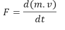
By calculating the change in momentum, it is possible to calculate the forces applied on the turbine blades.
Step 1:
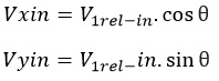
Find the x and y components of the relative inlet velocity vector using trigonometry:
Step 2:
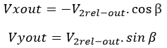
Find the x and y components of the relative outlet velocity vector (exiting velocity):
Step 3:
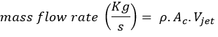
Find the force exchanged between the jet flow and the turbine blade in the x-direction. The force is equal to the mass flow rate multiplied by the change of velocity in the x-direction. Moreover, in order to calculate the mass flow rate, we should multiply the density of the fluid with the cross-sectional area of the jet flow and then with the scalar value of the entering velocity:
Step 4:
Find the force exchanged between the jet flow and the turbine blade in the y-direction by repeating the same process as in Step 3:

Step 5:
To find the total force applied to the turbine blade we should calculate the resultant force:
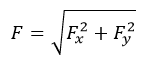
To find the inclination angle (α) of the resultant force:

How to Calculate Relative Velocity
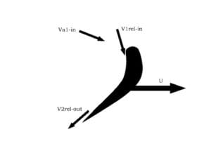
While a turbine is operational, the blades are revolving around an axis at a specific speed. To calculate the effective force applied on the blades it is necessary to calculate the relative velocity of the incoming jet. The calculation has to identify the magnitude and direction of the relative velocity using the velocity triangle method.
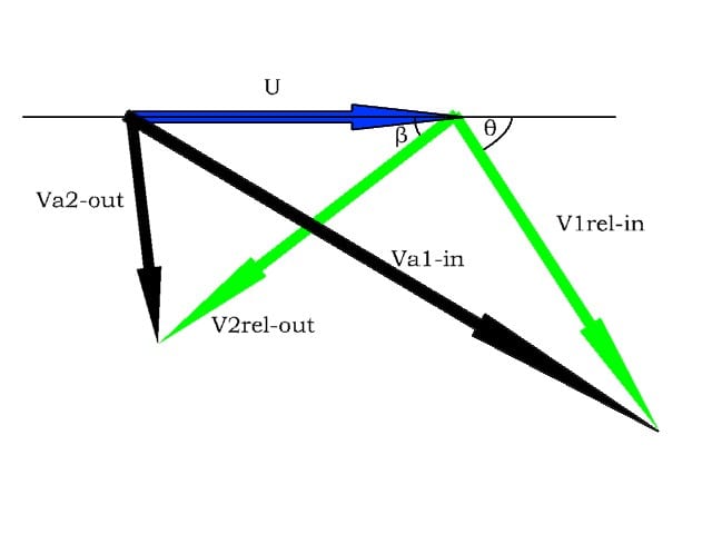
U: The velocity of the blade
Va1-in: Absolute velocity of entering jet flow
Va2-out: Absolute velocity of exiting jet flow
V1rel-in: Relative velocity of the entering jet flow, which is the summation of U and Va1-in velocity vectors
V2rel-in: Relative velocity of the exiting jet flow, which is the summation of U and Va2-out velocity vectors
Power Output
The driving force of the turbine is:

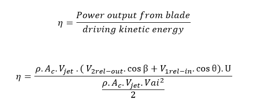
Calculating Efficiency of A Water Turbine
To calculate the efficiency of water turbines, we should find the ratio of the power output with respect to the driving kinetic energy.
SI Units
Force (: (N)
Density (: (kg/m3)
Cross-sectional area of the jet stream (Ac): m2
Velocity: m/s
Angles: Degrees
Mass flow rate: Kg/s
Conclusion
The essential difference between turbines and pumps should now be clear; as turbines are used to create energy out of the fluid movement, and pumps are used to create fluid movement using energy. Calculating the efficiency of a water turbine requires many physical equations, concluding with the ratio of power output from its blades over the driving kinetic energy.
Using these results, the water turbine design can be optimized or compared to other types of turbines in order to choose the right one suited to an application. While the laws, calculations, and equations mentioned are, in some cases, centuries old, they are still relevant today and are enabling designs that will shape the future. And with new methods like simulation and computer-aided engineering, engineers have simpler, more intuitive, and more efficient tools they can use in the design process.
Interested in more resources about turbomachinery? Read the story about how American Wind optimized its micro wind turbine with CFD.