This article focuses on explaining the difference between CAD and CAE. But let’s first explain what exactly CAD is.
CAD and CAE What is CAD?
Not too long ago, before CAD was introduced, engineers made their drawings and calculations by hand. Today, that would be considered a struggle. Engineers only drew three different views on their sheet of paper, and they had to simplify their product in order to make calculations of its behavior if external forces were applied. With the introduction of computer-aided design (CAD) software, it was suddenly possible for engineers to create accurate 3D models. With further technological advancements, these 3D models can now be analyzed using computer-aided engineering (CAE) software.
CAD vs. CAE Tools From Manual to Automated Calculations
On the way to being a qualified mechanical engineer, the first thing students learn is how to solve mechanical problems. In this example, our mechanical problem is the need to find out how wind affects the Olympic Tower in Munich.
The first thing we do is simplify the model. Details and features of the tower (including the restaurant and antenna) that might not be needed for a rough mechanical calculation are going to be eliminated.
At first, we make a rough drawing of the tower, which in our case is a simple line on the paper. We estimate the wind as a constant force at the tip of the tower with the goal of the calculation being to get the momentum at the bottom of the tower. The equation would simply be the force of the wind times the height of the tower.
This model is extremely simplified. Everyone—including the person that is responsible for the success of the project—knows that in reality it is much more complicated than that, and they would want a more sophisticated calculation of the problem.
Counterarguments for the easy approximation we did are:
- The Olympic Tower is not a two-dimensional line drawn on a paper, but a complex three-dimensional geometry.
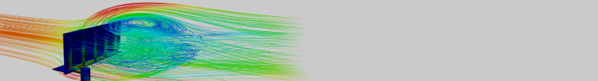
- The wind is not a single, constant force, but rather a dynamic force that causes turbulence and other effects.
To calculate this, we utilize the power of computer-aided engineering (CAE).
SimScale’s CEO David Heiny tests the capabilities of cloud-based simulation to solve an engineering problem. Fill out the form and watch this free webinar recording to learn more!
CAD vs. CAE The Difference Between CAD and CAE
CAD is the abbreviation for computer-aided design, which refers to using a computer to visualize a product idea. CAE is the abbreviation for computer-aided engineering, which is the analysis of the designed visualization. In short, the difference between CAD and CAE can be put this way: CAD is for designing a product and CAE is for testing and simulating it.
The advantages of using computers in design, in comparison to old-school methods, are quite obvious. The main perks of 3D CAD software over 2D drawing include but are not limited to the following:
- A 3D version of the object can be created. Engineers and production workers can more easily understand the shape and the properties of the designed geometry. Furthermore, some geometries can be extremely complicated and difficult, if not impossible to properly understand without seeing them in three dimensions.
- Changes to the geometry can be very easily made because the software recalculates the product after every change. Moreover, the CAD program identifies and alerts you to any errors in your geometry that would, for example, cause a collision of moving parts.
- Probably the most important advantage is that a CAD model can be transformed into a mesh and then simulated for analyzing and testing purposes.
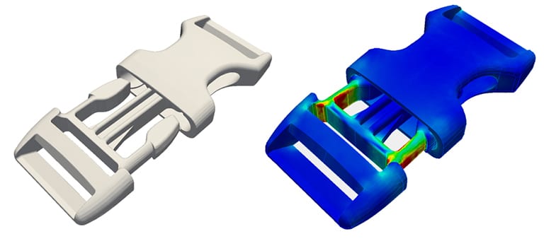
CAE tools also have a lot of advantages, such as:
- Not needing as many prototypes and driving down the overall development costs of the project.
- CAE reduces the potential for errors in design.
- The users avoid over-engineering since they can immediately see if the changes to the product design affect the performance, which allows them to decide early in the process whether it’s worth it to continue developing or if they should drop the design version after the first simulations.
- The effect of altering a few parameters on the product can be studied.
All of these benefits can help to reduce the costs and time to market for a product.

Meshing The Difference Between CAD and CAE: The Meshing Process
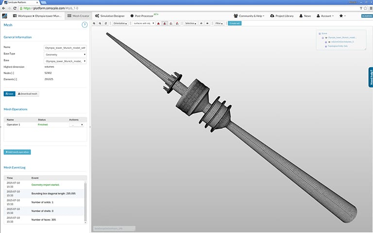
Mesh of the Olympic Tower Munich created with SimScaleSo let’s get back to the key point: what is the difference between CAD and CAE? At a first glance, the models used by CAD and CAE software almost look the same. However, a closer inspection reveals that they are fundamentally different. They both have the shape of the product, however, from a mathematical standpoint, they do not have a lot in common.
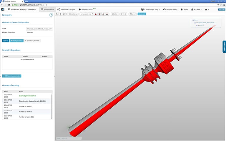
There are different ways of combining geometrical elements to form a 3D geometry. Most likely, CAD models are designed as an assembly of volumes or bodies with parameters like the density of the actual material. The model widely used for CAD modeling is a parametric model with a construction history. This provides the advantage of being able to change features retrospectively, which allows 3D objects to be built as a combination of geometrical shapes with parameters.
In a CAE environment, the CAD model is transformed into a mesh during pre-processing. The mesh either consists of cubes, cuboids or tetrahedrons, so generally polygon meshes. Therefore, it is legitimate to compare a CAD model to a vector graphic, whereas a CAE model could be described as a pixelated model.
CAD vs. CAE Calculation and Post-Processing
This clearly shows that you cannot just transform a CAD model into a CAE model. The modeling of spheres, for example, will be a problem you will face. It is impossible to do this with volumes that have corners, but if the single volumes of the mesh are small enough, it can be a good approximation.
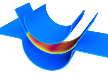
After the pre-processing is complete, the calculation starts. This differs according to the problem you need to solve and the type of simulation, such as finite element analysis, computational fluid dynamics, or thermal analysis.
In the previous example, after having designed the tower with CAD, a finite element analysis would be used to calculate the forces of the wind affecting the Olympic Tower.
After this step, post-processing has to be carried out to visualize the solution of the analysis. The visualization of the Olympic Tower looks like this:
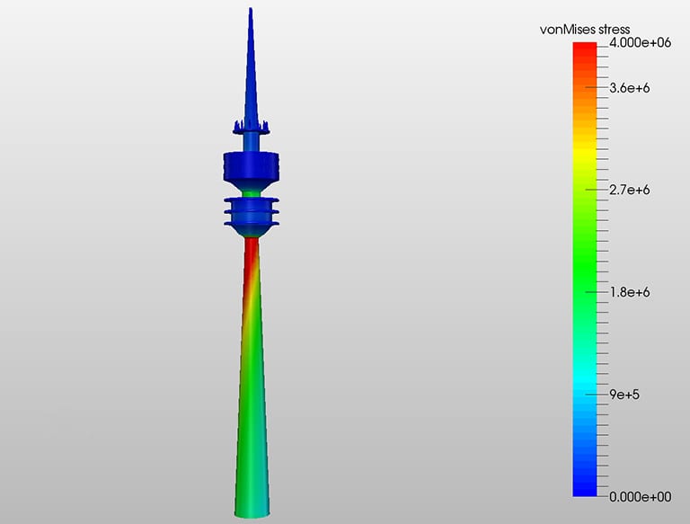
The engineer will want to simplify the CAD model because it will not be possible to process a perfect one, due to the lack of calculating power. In contrast, an engineer using a CAD model wants to create a perfect depiction of the model he has in mind. The approximations that are being made are highly accurate. Just think about the fact that the concrete column of the Olympic Tower is also not perfectly round but has small edges where the planking of the concrete was placed. As soon as this is completed, the next steps are creating the mesh and setting up the simulation. You can take a look at this project and see the results of the harmonic analysis and static analysis that were performed to identify the displacement and von Mises stresses produced in the Olympic Tower due to the wind pressure.
Online CAD & CAE How to Learn to Use Simulation Software
Now that we have discussed the difference between CAD and CAE as well as their advantages, the question is: how can a CAD user start using engineering simulation? There are several possibilities, including step-by-step tutorials, public projects and webinars.
To learn more about cloud-based CFD simulation with SimScale, download this features overview.
References
- https://www.cim-team.com.br/modern-electrical-engineering-blog/cad-vs-cae-vs-cam-what-is-the-difference
- https://feaforall.com/the-difference-between-cad-and-cae/
- https://www.cim-team.com.br/modern-electrical-engineering-blog/cad-vs-cae-vs-cam-what-is-the-difference
- https://netzkonstrukteur.de/warum-unternehmen-3d-cad-nutzen-sollten-teil-1/
- https://www.designtechcadacademy.com/knowledge-base/computer-aided-engineering
- https://de.wikipedia.org/wiki/CAD#Mechanische_Konstruktion
- https://feaforall.com/the-difference-between-cad-and-cae/