When Marc Wheeler took over teaching the Principles of Engineering course to 11th and 12th grade students at Harmony Magnet Academy, his goal was to find a way to incorporate computer-aided design (CAD) and finite element analysis (FEA) into the curriculum.
Balsa Wood Bridge Design
The opportunity to introduce these two topics presented itself in the bridge design unit where the students were tasked with designing and building their own balsa wood bridges. The goal of this unit is to use engineering principles to construct a bridge that can withstand the greatest weight before it fails.
One of the requirements is that the students must analyze forces in their bridge models. “Since the bridges are statically indeterminate, using FEA software is the only way to do this and get useful results,” explains Marc.

The design process encourages the students to think like engineers. It requires them to explore different bridge types, consider the material properties of the glue and wood members, and understand the load path to improve the strength of their design.
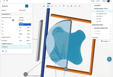
In Marc’s class, after selecting the basic bridge type, the students used the Inventor Autodesk software to model the bridge in 3D. After this, the 3D CAD model was uploaded to SimScale to simulate the loads, visualize how the bridge would deflect, and predict the most likely points of failure using finite element analysis.
Setting Up the Simulation
The simulations were set up in SimScale using the following steps: mesh generation, application of loads and constraints, material assignment, simulation run, and visualization of the results. Let’s take a look at one the projects in more detail:
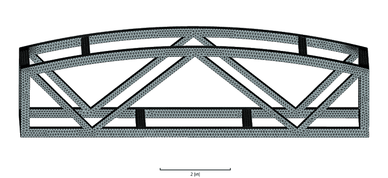
Mesh Generation
The mesh was created in SimScale using the tet-dominant meshing algorithm with a moderate fineness and second-order elements that perform better when bending. [expand]
Load
A load of 100 lbf was applied to the top members of the bridge.
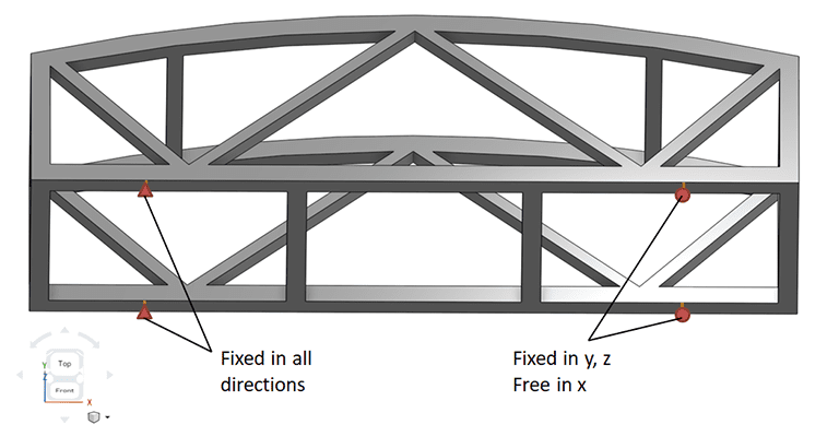
Constraints
The model was fixed in all directions at the left support and allowed to move freely in the x-direction at the right support. This allowed the bridge to expand laterally as the load is applied, just like it would in an experimental test.
Material Assignment
The material that the bridge was constructed from, balsa wood, was applied to the model. Wood can be a challenging material to use in simulations because it has unique and independent mechanical properties in the longitudinal, radial, and tangential directions.
Based on the information provided in The Wood Database, the following material properties were assumed for the simulation:
- Young’s modulus (elastic modulus): 500000 psi
- Poisson’s ratio: .018
- Density: .005208 lbm/in³
Simulation Results
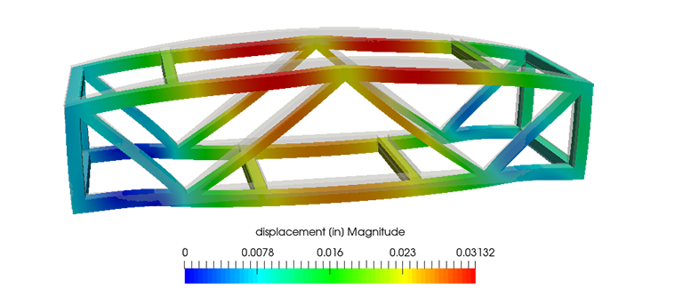
The simulation results provide us with an idea of how the bridge will behave under an applied force. As the force on the bridge increases, so will the downward displacement.
The greatest displacement was observed to be .03123 inches on the top members of the bridge.
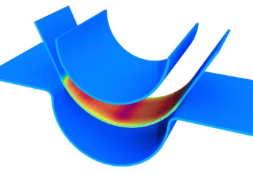
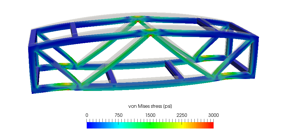
Secondly, the stresses in the bridge were observed. The von Mises stresses help us to identify the critical bridge members that might be the first to fail based on the current design.
Sign up & check out our SimScale blog for much more!

Experimental Results
The students’ bridges were finally put to the test using the Structural Stress Analyzer, a tool that directly measures force and displacement. The results for the very same bridge that was simulated in SimScale are pictured below.
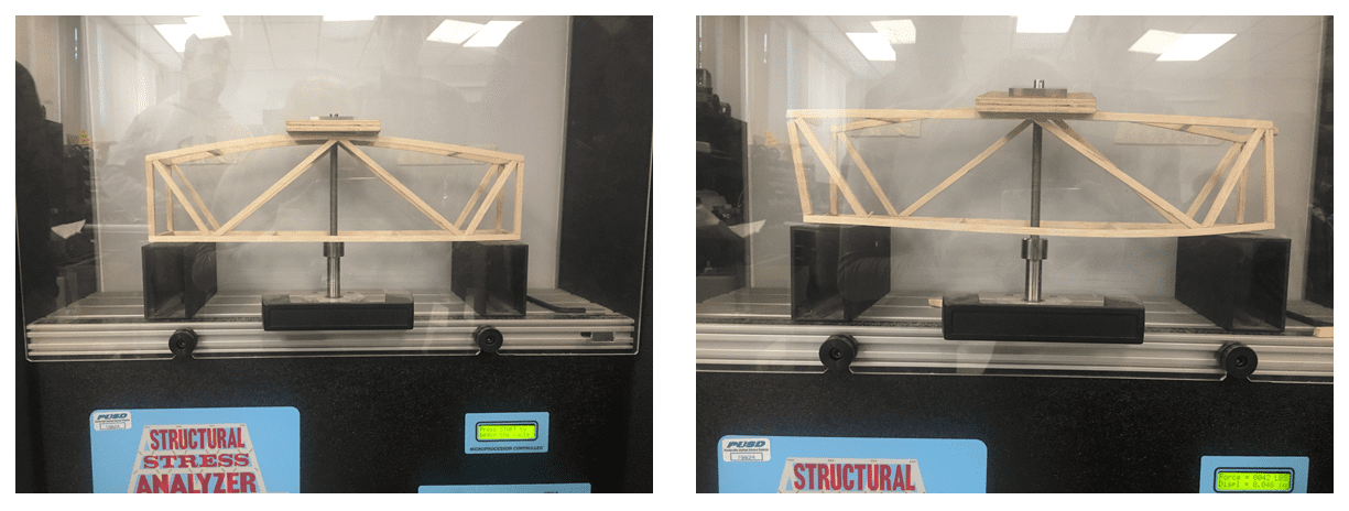
The wood bridge withstood a load of 42 lbs and a displacement of .048 inches before it failed. We can compare this to the simulation results and ask why they don’t match exactly.
The answer comes down to a number of contributing factors. Firstly, it is difficult to know the exact material properties of the balsa wood that the bridge was built with, especially in terms of stiffness and density. Additionally, defects in the wood or improperly glued pieces can weaken the bridge unexpectedly which is not accounted for in the simulation results.
Moreover, a lack of symmetry in the constructed bridge versus the perfect symmetry of the simulation model also leads to different deformation characteristics under the load.
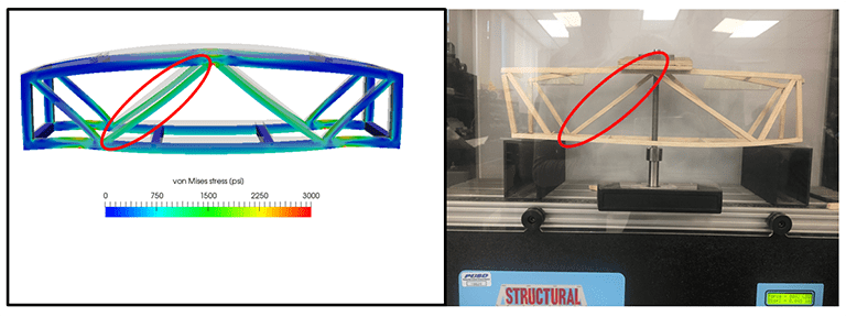
The main benefit of FEA is that it allows students to easily visualize and analyze the structural loading. As one will notice, the bridge member under the highest stress in the simulation is congruent with the actual point of failure in the bridge.
Teaching with SimScale
Many education studies show that a student’s learning improves when they can see things and work with their hands [1]. It’s important that professional engineering analysis tools such as SimScale are not just reserved for engineers, but are actively incorporated in the classroom to teach the principles of engineering to high school and university-level students.
For Marc, by giving his students more exposure to FEA software in high school, he hopes to provide them with an understanding of the value of simulation in engineering and demonstrate ways to use the software should they choose to pursue engineering as a career.

References
- https://tiij.org/issues/issues/3_3/3_3j.html