This is a common question that haunts most designers: what is accuracy in FEA or CFD simulation? And just how accurate are these computer models? With rapidly advancing technology and growing computer power, simulations have started to play a major role in product design and the optimization process.
In the early days of modern technology, simple hand calculations, along with data tables and factor of safety calculations, were used on a daily basis. However, such calculations were insufficient, leading to the development of FEA and CFD simulation, which were originally created for the design of aerospace and civil engineering structures. Over the last four decades, FEM and CFD simulation have been widely applied to applications beyond these areas. In the last decade, in particular, these numerical techniques are being applied to multiphysics applications such as biomechanics and electromagnetics. As the industry has started to use these technologies more extensively, one question that many often ponder is related to their reliability.
To summarize, FEM and CFD are just numerical techniques that can solve several partial differential equations. Most physical phenomena are described by partial differential equations: Fluids (Navier-Stokes), Electromagnetics (Maxwell), Solids (Equilibrium), Thermal (Fourier), etc.
The flashy pictures we’ve become accustomed to in popular animations and videos are the result of solutions to these PDEs. However, these are specific solutions to a particular boundary condition. Similarly, simulations are also solutions to these PDEs. However, simulations are generic ones to general boundary conditions, whereas numerical methods use discretization of the entire region to solve the problem.
Simulation Accuracy for the User
Most often this is a question of the user who needs a particular component to be designed.
Firstly, it is necessary to fully understand the application where the component shall be used. Are the conditions static or dynamic? Is it subjected to fatigue or cyclic loading? Considering the correct form of a simulation is the first step in ensuring simulation accuracy.
One of the most common causes of failure is fatigue. The structure weakens with each cycle of loading, and eventually, over millions of cycles, the structure suddenly fails. Such failures are catastrophic in nature. In this instance, static or dynamic analysis is only as an order of magnitude approximations.
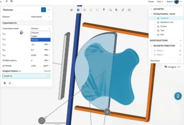
As the process progresses, the material properties need accurate calibration and comparison with experiments. In addition to using an appropriate material model (linear, nonlinear, elastic, hyperelastic, plasticity, viscoelasticity, etc.), the numbers used for these models need to be appropriately fitted with experiments. Most often, inaccuracies arise when data is “extrapolated”. Interpolation is acceptable, but extrapolation is really dangerous.
Thus, the customer can ensure that the simulations are accurate and within permissible limits by providing the designers with:
- Exact application of the designed component
- Typical loading conditions
- Actual material/material properties/experimental data for the material to be used
Simulation Accuracy for the Designer
On one end, small-scale companies generally prefer to outsource simulations of components to medium-scale companies. On the other end of the spectrum are the multinationals. These companies have dedicated in-house design departments who specifically use simulations like FEA and CFD. Alternatively, they outsource the work to the medium-scale companies. So the designer here refers to the latter.
What do these designers need to concentrate on? What is simulation accuracy and how can it be improved? The factors from the perspective of the designer include:
- Appropriate mesh accuracy
- Mesh independence
- Element technology
- Validation
CAD geometries are stored as B-splines, etc. These are curves that are used to represent the exact geometry. Later in the simulation process, these CAD geometries are discretized using FEM meshes. A whole new field called isogeometric analysis has developed in the last decade, where FEM or CFD simulation is done using the actual CAD geometry and eliminating the entire meshing process. However, this is still nascent and is something to look forward to in decades to come.
One of the prominent questions to ask is if whether the mesh fits well with the geometry. In general, second-order meshes can replicate curved geometries, thus they are more suitable for accurate meshing than linear elements. In addition, the distortion of elements can also reduce the mesh quality substantially, which also affects the accuracy of the obtained solutions. Some tips for meshing in FEM can be found in the article “How to Mesh your CAD Model for Structural Analysis (FEA)“.
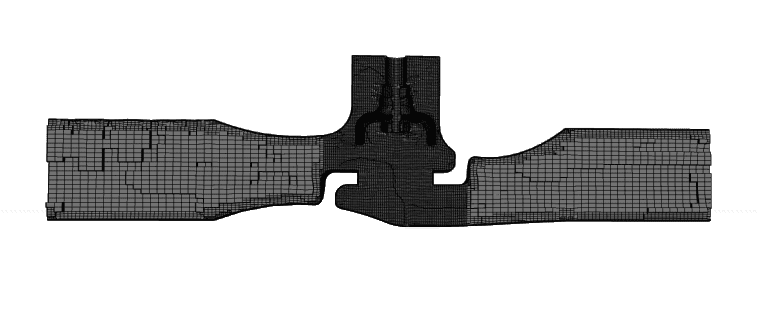
The second aspect of consideration is regarding mesh independence. Both FEA and CFD simulation require accurate meshing and are, by default, mesh dependent. However, meshing is an approximation of the actual model into a discretized finite model. Thus, complete mesh independence is never possible. However, it is important to check mesh convergence of the results. This requires doubling the mesh density and checking for changes in the results. It is pertinent to remember here that nodal degrees of freedom (like displacements, temperature, etc. in FEM and velocities and pressures in CFD) will always have converged. However, the post-processing quantities like strains and stresses do not converge. This is especially true in the presence of singularities. Check the latest article on the SimScale blog titled “Mesh size influence on the mechanical stress concentration” for more information on regarding FEM in the presence of singularities.
Later in the process, the type of element used will again influence the result. The developer can help the designer to find suitable solutions in relation to this particular aspect. For example, most linear elements demonstrate volumetric locking effects when used in problems involving compressibility (like rubber materials, plasticity, etc.). Similarly, using solid elements in thin structures can lead to shear locking. Solutions to these problems are available through the use of different types of elements, and it is necessary for the designer to understand the right usage for their problem to improve simulation accuracy.
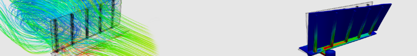
Boundary conditions that replicate the right loading conditions and material models that represent the actual behavior—as provided by the customer—are definitely aspects that are necessary to ensure realistic simulation results. Understanding the entire workflow and its requirements can go hand-in-glove to creating realistic simulations. A simple sample can be found in the article “CFD Workflow Guide: How to Set Up a Fluid Dynamics Analysis“.
Finally, validation is the part the most designers forget. Some important questions to ask here include: Is there any data for the application being designed? How well does it compare with the experiments? In that case, what parameters in the model need to be tuned to make it more realistic? Validation plays an important part in ensuring that all the numbers used are realistic, thus ensuring a simulation result as near to reality as possible.
Finally, the Developer
Finally, the developer—the person doing the dirty work of developing these algorithms! Most problems representing reality are nonlinear in nature, hence the convergence of developed algorithms play a pivotal role.

The developer needs to work on algorithms that are robust in nature and, where necessary, add appropriate error messages that the designer and customer can comprehend. Unlike SimScale, most commercial software does not allow the designer to meddle with the convergence thresholds. Suitable “caution” boxes need to be added such that the precautions can be exercised by the designer.
How Does the Future Look Like for FEA and CFD Simulation?
As we advance, concepts like machine learning are becoming more and more common. In the near future, we will have computer programs that can guess what the user is trying to do and automatically suggest caution. Another aspect that has recently been kicking dust is automation, where the designer tells the program the problem of interest and the computer sets up the simulation environment completely—even on the fly!
Judging the accuracy of the simulation eventually necessitates that everyone in the chain understands some basic aspects to judge if the results are realistic or just a pretty picture. A recent SimScale article “When Is It Just a Pretty Picture?” provides a small glimpse into the post-processing world for FEA.
There exists great potential that is yet to be tapped completely. Caution and judgment are necessary at each step to ensure the accuracy of the results and a realistic FEA or CFD simulation!
SimScale’s CEO David Heiny tests the capabilities of the cloud-based CAE platform to solve a real-life engineering problem. Watch this free webinar to see how!
If you’d like to learn more about the SimScale cloud-based platform and its capabilities for FEA and CFD simulation, download this features overview.