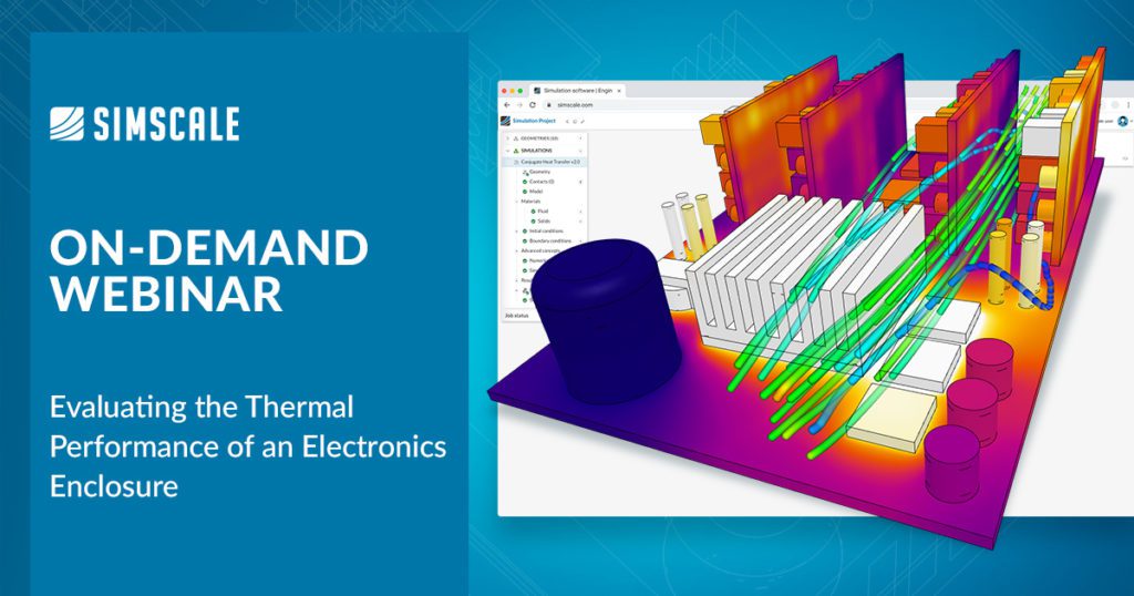
SimScale is a cloud-native engineering simulation platform used to understand electronics enclosure cooling and heat transfer analysis. Accessed via a web browser and used by engineers globally, the SimScale platform provides intuitive simulation solutions and workflows for electronics designers using both active and passive cooling strategies. These workflows include importing CAD geometry, meshing, simulation, and post-processing results. This article describes a forced convection cooling example that is available in the SimScale public projects library.
Cloud-Native Engineering Simulation for Thermal Analysis
SimScale offers multiple analysis types for engineering simulation including conjugate heat transfer (CHT) capabilities coupling solid and fluid domains and also leverages automated parallel computation capabilities in the cloud. These capabilities give engineers and designers the benefits of:
- Faster design cycles and electronics performance insights
- A full exploration of multiple design iterations in parallel
- Reduced costs and time investment in the costly prototyping phases
- In-platform CAD editing for streamlined simulation workflows
All electronics devices generate heat that must be managed to avoid overheating and component failure. The SimScale platform can be used to simulate and optimize multiple electronics enclosure cooling strategies and common features, including:
- Natural and forced convection
- Air and liquid cooling
- Fan modeling
- Anisotropic materials (PCB)
- Thin layer resistances
- Power networks
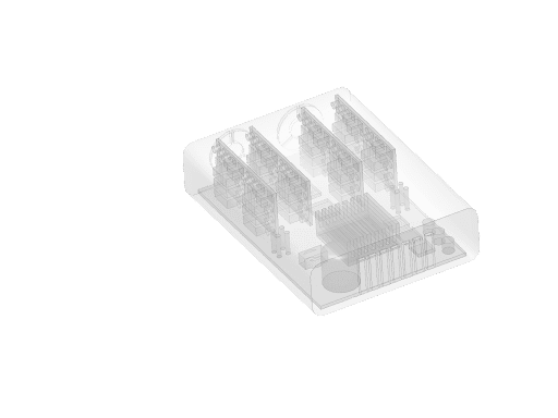
The conjugate heat transfer (CHT) v2.0 analysis type in SimScale enables heat transfer analysis between solid and fluid domains by transferring energy (thermal) at the interfaces (contacts) between them. This means that the model must contain at least one fluid and solid region. In most cases, a CAD geometry will not have a fluid domain assigned as default. The SimScale CAD mode provides a flow volume extraction tool to do this. Typical applications of CHT analysis type include analysis of heat exchangers, cooling of electronic equipment and electronics enclosures, LED luminaire design, and similar cooling and heating systems. The upgraded version of the CHT analysis type in SimScale (CHT v2.0) is more stable and provides faster convergence as the energy equation is strongly coupled between the solid and fluid regions. With the upgrades, both incompressible and compressible flows can now be modeled including the impact of radiation heat transfer. Both fluid and solid domain mesh are required for a CHT simulation with clear definitions of the fluid and solid interfaces or contacts. With these interfaces properly defined, the mesh is automatically taken care of in SimScale.
Avoid Electronics Enclosure Overheating with Active Cooling
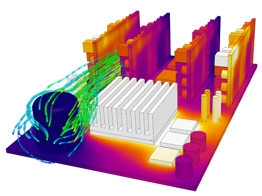
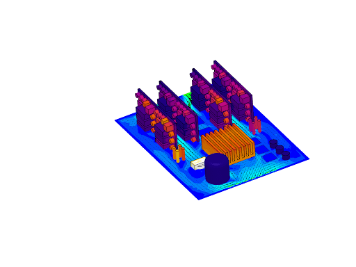
In the example of the forced convection cooling case, the key design considerations that are explored include the velocity and temperature distributions across electronic components and their dependence on fan (forced convection) inlet speeds. Multiple heat sink designs can also be simulated in parallel for comparison.
The case in question is the heat transfer analysis (cooling) of densely packaged electronics inside an enclosure. The simulation setup is as follows:
- A conjugate heat transfer (CHT) simulation is used to model conduction in solids and forced convection (air).
- There are two inlet fans (simulated) providing forced convection into the electronics enclosure. Two velocity inlet boundary conditions where the fans would be on one end, give a ventilation rate of 0.014 m3/s per fan at ambient conditions (20℃). The other end of the enclosure has openings using a pressure outlet boundary condition.
- The fan flow rate is constant. For more detailed analyses, a custom fan performance curve can also be uploaded into the SimScale platform.
- Materials including silicon, tin, copper, aluminum, and polylactic acid (PLA) have been assigned to the electronics enclosure, boards, and components using the extensive material library. Custom materials can also be defined.
- Heat transfer coefficients (HTC) are applied to the walls.
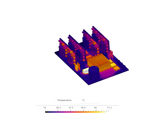
- Electronics components receive electrical power and generate heat (e.g. resistive losses). The heat load from each component can be defined by assigning an absolute power source in watts. Various thermal loads and power sources from IC chips, resistors, etc. have been defined totaling 100 Watts with the single largest load being the main CPU at 40 Watts.
Simulating Heat Transfer for Better Electronics Design
The simulation takes approximately 30 minutes to run. Because of the high-density power electronics in a confined space, we observe high temperatures on some of the components because not enough airflow is reaching those parts. The SimScale platform allows users to easily alter the flow rate, reposition the supply fans, or employ a combination of the two.
A design study on the heat sink, using various materials, or altering the number and spacing of fins, can also be undertaken at this stage. Importantly, when users set up and run these alternative designs, running all of them together simultaneously would still only take 40 minutes, saving considerable time when compared to sequential runs. Simulating heat transfer analysis at the early stages of design can give designers more options to finalize a design before spending money on costly prototyping.
Evaluate the electronics enclosure cooling design and learn more about simulating forced convection cooling from a web browser, in our on-demand webinar, Thermal Analysis of an Electronics Enclosure: Forced Convection Simulation.