In order to ensure sustainable living environments, it is essential to assess both the design of HVAC equipment and the effectiveness of ventilation strategies. For a good ventilation and heating strategy, designers must first understand airflow and indoor air quality, examine how external wind conditions might affect indoor thermal and ventilation conditions, and ensure their designs comply with local building regulations. By running Computational Fluid Dynamics (CFD) simulations easily in the cloud, designers can derive design insights and evaluate the effectiveness of their ventilation strategy at the early stages of the design process.
Below, we cover two case studies that demonstrate what we’ve learned from over two years of rapid ventilation design assessments. These techniques enable architects and engineers to quickly and accurately predict air movement and air quality, determine HVAC sizing, and assess ventilation strategies.
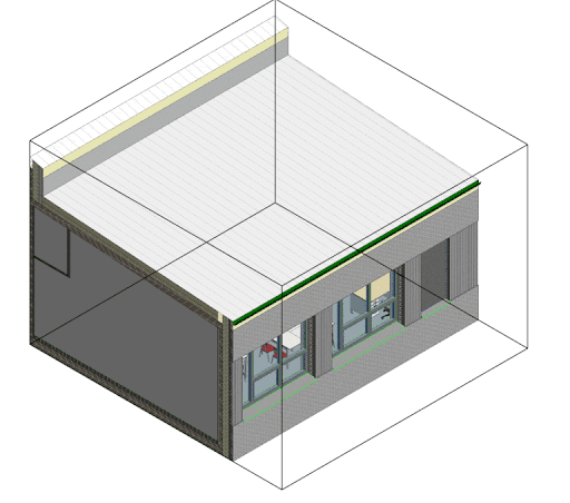
Case Study 1: Classroom Ventilation Strategy
In this case study, the aim was to assess the heating and ventilation strategy of a classroom and to ensure that the design complied with the Passivhaus environmental and energy metrics. In various HVAC systems, CFD can be used to determine which parameters will have the largest impact in relation to improving indoor air quality and living conditions. Some of these parameters within this case were U-values for different parts of the room (due to the different materials being used), radiation sources to represent solar gains, occupants, and additional insights the team wanted, such as the quality of air.
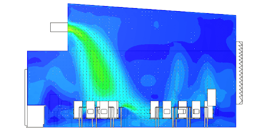
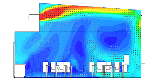
Once the base design was simulated, the architects faced two challenges: Firstly, due to the inlet, the air was drafted on top of the occupants in a rough manner, which would create a significant amount of thermal comfort disturbance. And secondly, existing air within the classroom was observed to be of low quality with high CO2 levels. Adjustments would be required to make the design more efficient, with increased air quality and better thermal comfort, but without additional energy loss.
In order to solve these issues, architects came up with different designs to improve the air supply strategies and validate cases. They ran different configurations in parallel to converge on the optimal solution. For each of the design variations, the team compared temperature distribution within the space and assessed air quality by means of CO2 concentration inside the room.
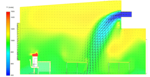
In the first design change of the base case, different HVAC inlet configurations were tested. By utilizing the guide vanes and having a high wall diffuser, inlet air was pushed towards the ceiling. As the air hit the wall it allowed for circulation inside the room and solved the first issue of occupant discomfort.
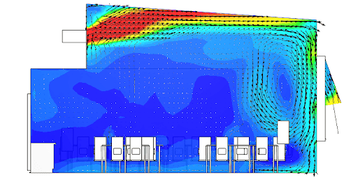
In the second design change of the base case, the designers focused on solving the low air quality issue inside the room. In order to reduce the amount of CO2, the high wall diffuser setup was combined with various window opening scenarios to measure the impact on ventilation and indoor air quality. In the end, the combination of a top-hung window opening and a high wall diffuser setup was found to increase air quality and reduce CO2 by improving the flow pattern within the room. This scenario satisfied both air quality and thermal comfort criteria.
Case Study 2: External Wind Conditions and Ventilation
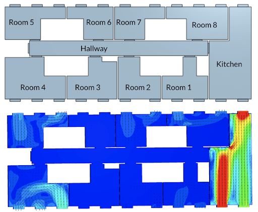
The goal of this case study was to assess the effect of external wind conditions on ventilation strategies. By taking into account wind conditions, designers can ensure their study is as close to real-world scenarios as possible. The goal here was to assess ventilation in every room of an apartment building when external wind impacts are considered.
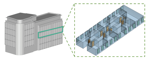
The process to derive the internal conditions for this particular case was started by modeling the building together with its surroundings in a Pedestrian Wind Comfort (PWC) analysis. With a PWC analysis, we are interested in assessing the wind comfort criteria for various wind directions. For this internal case study, the interest was in one particular direction so that it could be applied directly to the building. We focused specifically on observing how the wind from the southwest direction would affect the third floor of the building. Pressure tappings were applied from the external wind study to the windows and, to simulate a life-like scenario as much as possible, internal door leakages were also considered within the setup.
As the base design was simulated, engineers focused on answering two main questions. First, whether the natural ventilation of one window open was sufficient for the building or if forced ventilation was needed. And secondly, if CFD could help in deciding the correct ventilation strategy.
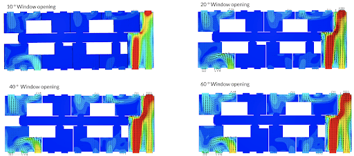
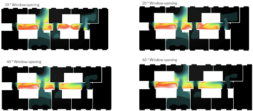
After getting the results of the base case setup, different scenarios with wider window openings were simulated to compare the mean age of air within the room. By increasing the opening angle of the window, a one-sided improvement in the ventilation was observed. But after some duration, no matter how much the window was opened there were no more significant changes in the ventilation inside the building.
Mean age of air plots can give us a good understanding of where the air is stagnant and where there is a good amount of ventilation inside of a building. As the plots were checked, a pattern was observed. Rooms on the corners and the kitchen were well ventilated, whereas the rooms in the middle were not well ventilated.
In light of the results obtained from the CFD analysis, it became easier to focus on potential reasons for poor ventilation in some rooms and solutions on how to improve it. For example, even though rooms six and seven looked very similar to each other, the conditions of airflow and ventilation were not the same. This was due to prevailing wind conditions.
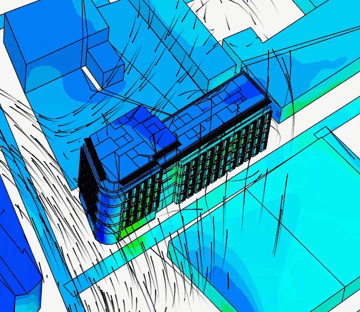
The animation visualizing the wind results shows a large amount of wind coming from the right-hand side and hitting the side of the building where the kitchen is located. This helped with both ventilation in the kitchen and with the cross-ventilation, as a high degree crossflow was entering from the window and then going out of the other side. On the other side of the building, the air was creating a recirculation zone within rooms five, seven, and eight. This was causing single-sided ventilation with air entering and leaving if the other window was also open. This explained the reason why even though rooms six and seven were similar in structure, room six was not as well ventilated. Room six lay in a region where the recirculation ended and also the interaction between the wind effects from the surrounding buildings started. There was a dead zone created in front of the building and that caused insufficient air to pass through.
In the end, CFD studies determined that natural convection was not sufficient for all rooms of this building. In most cases, opening the windows increased the ventilation, but for the corridor and some of the rooms, like room six, additional forced ventilation is needed to satisfy the air quality standards.
Cloud-Native Simulation for Ventilation Strategies
As shown in these two case studies, CFD analysis is necessary for understanding and predicting the effectiveness of natural and forced ventilation. As a next step, CFD analysis can even inform design decisions on the best sizing for HVAC equipment for a particular building or room. This not only helps avoid undersizing or oversizing HVAC equipment but also ensures proper ventilation, thermal comfort, and indoor air quality while optimizing designs for less energy loss.
Cloud-native CFD analysis enables engineers to solve for internal and external flows, study indoor and outdoor thermal comfort, and scale HVAC device-level simulation results from room-level to building-level and beyond.