Natural frequency analyses are used to determine the dynamic properties of a system and to identify its resonant frequencies. Some frequencies can cause elements to ‘sing.’ Imagine the sound of a guitar string being strummed. Because we understand a guitar string’s resonant frequencies, we are able to harness it, and subsequently make music. This can also be exampled by microwave ovens. Microwaves in microwave ovens have an equal frequency to the frequency of water molecules. As these molecules are oscillated and gain kinetic energy, the temperature of food rises.
At the same time, we can also use this knowledge of natural frequency to dampen an object’s resonant frequencies and vibrations. As engineers, natural frequency analysis, or modal frequency analysis, of planned structures or buildings is imperative to avoid disasters. For example, the construction of the Tacoma Narrows Bridge in 1940 failed to take into consideration the bridge’s natural frequency, and as normal wind speeds produced an aeroelastic flutter, the suspension bridge disastrously collapsed after 5 short months. In the case of the Tacoma Bridge, proactively dampening the bridge’s natural frequency would have proven to be a strategic design move.
How to Use CFD and FEA Together
With SimScale, using both CFD (computational fluid dynamics) and FEA (finite element analysis) is possible on our platform. While CFD can simulate airflow on and around a structure (i.e., wind loading) FEA simulates what the acting forces do internally to that same structure (i.e., vibrations). The case below evaluates a building using FEA for natural frequency analysis to determine its modal frequencies, and then compares the findings with the results of a CFD vortex shedding simulation.
Learn how to leverage the cloud-based SimScale platform to optimize your design based on accurate results and ensure pedestrian wind comfort and safety.
Case Study: Skyscraper Simulation with CFD and FEA
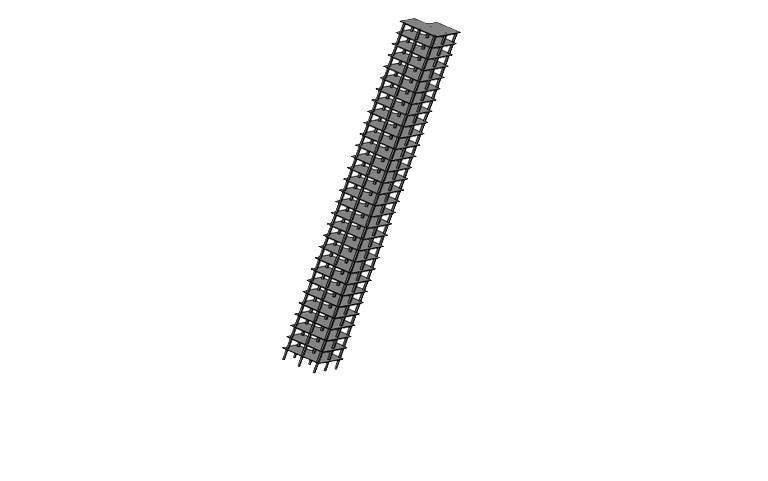
The project features an 80m structure with 30 floors at 2.5m intervals, 8 columns across the entire length, and is presumably planned to be built in an existing cityscape. The building is constrained only at the bottom with fixed supports in the ground, and is made entirely out of concrete. This was an assumption for the sake of testing.
FEA Simulation for Natural Frequency Analysis
The initial aim of the simulation project is to solve two questions using frequency analysis: What are the modal frequencies? And how could the wind loads on the building excite the structure?
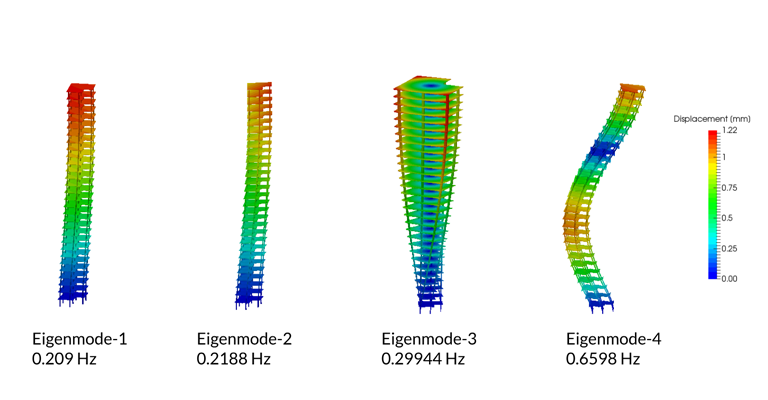
In order to determine this, FEA is first needed to determine the frequency response, or modal frequencies (eigenmodes) of the structure. The simulation is shaded by displacement where blue represents zero displacement and red represents a large amount of movement. This visualization is important in pinpointing where the design needs to be changed if it is deemed necessary.
Initial Modal Frequency Findings with FEA
The simulation took 9 minutes to run in total, giving exceptionally quick results. This included a graph of frequencies the building is going to respond to, which can later be compared with the CFD simulation findings.
The first 4 modes listed show how the structure is predicted to move at these particular eigenmodes. As you can see in the image below, the simulation revealed that the structure’s movements are very varied.
To further delve into the current design dilemma, CFD simulation is then used to calculate and predict vortex shedding and the forces on the structure.
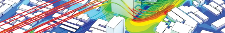
CFD Simulation for Vortex Shedding Analysis
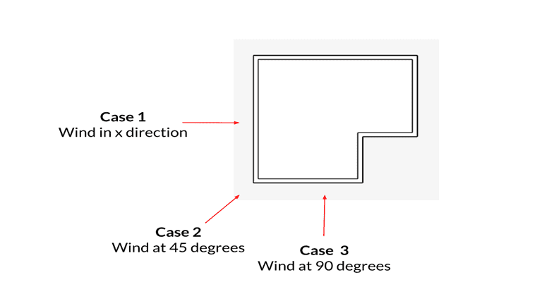
Similar to before, the project is set up with the same structural parameters. The simulation uses transient as well as turbulent flow using the incompressible LBM solver within the SimScale platform. The boundary conditions form the conditions of the virtual wind tunnel. An inlet profile is used where the inlet velocity is maxed out at 36.6m/s at 37m from the ground, the outlet is a pressure outlet, and the sidewalls have no friction. Three studies are then run for the purpose of the simulation; wind in x-direction from the left, at a 45-degree angle, and finally at a 90-degree angle. The simulation predicts the vortex shedding frequencies for each wind direction, and once extracted, these frequencies are compared to the modes from the previous analysis.
Vortex Shedding Results
The simulation found that there are significant forces acting upon the structure, and large flow variations.
CFD vs. Frequency Response Results
In two particular modes, the airflow velocity would excite the natural frequencies, creating an obvious design flaw as the actual structure would move. Therefore, some design changes must be made.
Conclusion
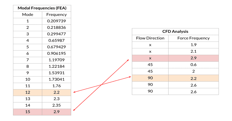
The FEA and CFD comparative simulations found that there were two modal frequencies that cross over with transient wind loads. This design could then be modified in two ways in order to mitigate vibrations and motion; through internal or external modification. Internal changes could include dampening the structure with a pendulum or similar dampening device. External changes could be the redesigning of the entirety of the structure, specifically looking at the 12th and 15th modes as noted in the table above, to alter the path of the wind around the structure and the lateral forces working against it.
Watch our recent webinar recording by filling out a short form here and check out our published slide deck for more information.


