Creating a reliable enclosure for heat dissipation in increasingly small electronic products presents engineers and designers with a variety of choices. How can one evaluate the options rapidly, and consequently select the optimal solution to suit the application? The answer lies in engineering simulation.
To illustrate how heat transfer or thermal simulation helps electrical engineers better anticipate the thermal behavior of an electronics enclosure, we hosted a free 30-minute webinar. Watch the recording below:

We tested and compared several design variations of a realistic industrial enclosure design of a controller and determined the superior design option for heat dissipation.
What is Heat Dissipation in Electronics?
The primary challenge of designing an electronic product is thermal management. The amount of heat produced accumulates within the enclosure, potentially damaging the electronic components. Such overheating not only reduces life expectancy but can also lead to product failure. This is true for small handheld devices, controllers, or heavier outdoor devices. The thermal behavior of such components always needs extra attention from the designer and cannot be neglected.
The common design elements aimed at increasing the thermal transfer capabilities of electronics through conduction include [1]:
- Thermal interface material (TIM)
These materials are used as filler materials in the gaps between the heat source and heat sinks. They are normally of higher thermal conductivity and help efficiently manage the thermal transfer across the system. - Heat sink
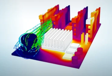
Heat sinks are the metal components that are in contact with the heat source to remove heat mainly through conduction and sometimes through convection or radiation. Simulating heat sink performance lets you compare materials and geometries before committing to a design. Usually, aluminum or copper are used as heat sink materials, as the thermal conductivity of such metals is relatively high and directly proportional to their heat dissipation efficiency. Since heat transfer takes place through the surfaces, heat sinks are specifically designed in various shapes to ensure large surface areas. - Heat pipes
Heat pipes are sealed copper or aluminum pipes or tubes containing a fluid. The liquid absorbs heat from the hot surfaces, boils, and enters a vapor state. - Thermoelectric modules
Thermoelectric modules are devices that employ the Peltier effect, which heats or cools components based on the application of a current to the device. These are always used in conjunction with the heatsink, without which the device might overheat and fail. - Thermal grease or adhesives
Thermally conductive adhesives or grease is another unique heat transport technique. One of the main advantages is that they bond components together that cannot be bonded mechanically.
As is evident, a designer has a lot to choose from. However, it is not easy to determine the right combination of components to ensure reliable and efficient heat dissipation, while keeping the product as compact as possible. This is where simulation can offer valuable insights.
Heat Dissipation Simulation
One of the best approaches a designer can take to overcome this problem is to run a thermal simulation on the electronics enclosure before the actual product is manufactured. This simulation can help find answers to many critical questions: How effective is the cooling system? What possible design changes need to be implemented? How does the selected material impact the heat transfer behavior? And many more, depending on the nature of your product.
The need to manufacture safer and more compact electronic devices is challenging engineers across the globe to create extraordinary designs. In the traditional design process, the only way to ensure the durability of a novel electronic product is to perform a high number of design iterations until all criteria are met. This implies a high number of physical prototypes and a time-consuming and expensive physical testing process.
In addition to the number of design iterations, the stage at which design changes need to be implemented is equally important; the earlier in the overall process, the more cost-effectively a design change can be realized. The later the stage, the scope of possible design changes narrows drastically, with only small, incremental design modifications possible.
Of course, physical tests cannot (and should not) be entirely eliminated from the product design process. Physical and virtual prototyping are not mutually exclusive—they are complementary. But with computer-aided engineering (CAE) the days, weeks, or months of physical testing are replaced with hours or even minutes of a simulation run.
The case study below illustrates how simulation can be a handy tool to help you predict the performance of a product and make smart design decisions.
Download ‘Electronics Cooling: The Ultimate Guide’ to learn everything you need to know about modern electronics cooling.
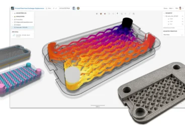
Thermal Simulation for Electronics
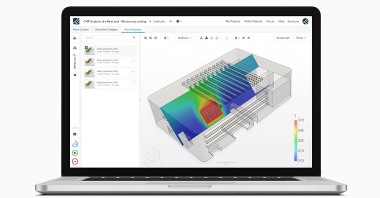
The purpose of this project is to perform an FEA thermal simulation on an electronics enclosure without the need for conjugate heat transfer analysis. This thermal simulation project is part of the SimScale Public Projects Library and is freely available to view, copy and modify. Three design variations of a realistic industrial enclosure design of a controller are considered:
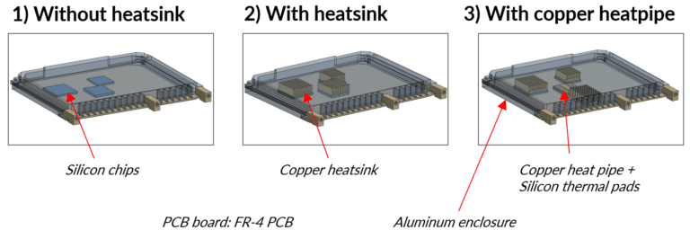
The above CAD geometries represent a complete assembly of a controller, which includes a printed circuit board (PCB), chips as the heat source, and an enclosure. Design 1 (left) is a basic design with silicon chips and an aluminum enclosure. Design 2 (middle) has a heat sink installed within the system, while Design 3 (left) has a heat sink, a copper heat pipe, and silicon thermal pads. Let’s see how they perform compared to each other.
Simulation Setup
The step-by-step simulation setup is detailed below:
Step 1. A linear transient heat transfer analysis type is selected to compute the temperature distribution and heat flux on the entire body.
Step 2. Tet-dominated element type meshing is used with local mesh refinements. A tet-dominated meshing algorithm is used to mesh the entire geometry. Additionally, local mesh refinements are applied to the areas of interest, such as the contact and small faces. This ensures that the corresponding elements are intact and produce accurate results. The figure below shows the meshed geometry with refinements.
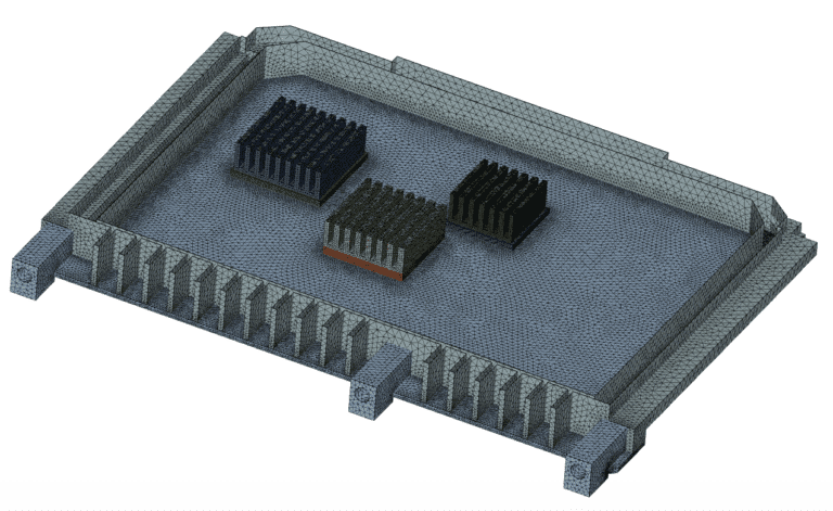
An automated mesh setting of moderate mesh fineness is applied to the chip volumes and fine mesh fineness is applied to the remaining faces of the body.
Step 3. On completion of the meshing, the points of contact are constrained by using bonded contact conditions between the printed circuit board (PCB) and chips, chips and heat sinks, and the PCB and enclosures. Following this, the materials are defined. The material properties pertaining to the following components are shown in the table below with their corresponding density, specific heat, and conductivity.
| Component | Material | Density kg/m3 | Specific heat [J/(kg K)] | Conductivity [W/(m K)] |
| PCB | FR-4 | 1850 | 600 | 0.3 |
| Chips | Silicon | 2330 | 705 | 0.2 |
| Heat sink | Copper | 8960 | 385 | 401 |
| Enclosure | Aluminum | 2700 | 897 | 235 |
Step 4. The boundary conditions are then set up with a volume heat source applied as a thermal load to the electronic chips and a convective heat flux to the outer surfaces.
Thermal Simulation Results: 95.8% Increase in Heat Dissipation
The temperature and heat flux distribution are visualized for all three cases:
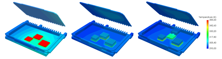
Temperature distribution
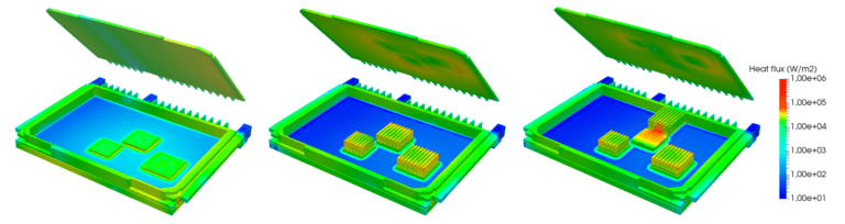
Heat flux distribution
From the simulation results above, it can be seen that the chips get extremely hot (715 K) in Design 1 due to the absence of a heat dissipation material. Heat removal here is mainly due to the aluminum enclosure material and the silicon chips are clearly overheated. At the same time, the heat sink in Design 2 helps remove the heat from the chips. Heat dissipation is 12.6% higher here compared to Design 1 (see the charts below for detailed numerical results).
The addition of highly conductive materials with a low convective heat transfer coefficient (the copper heat pipe in Design 3) increased the heat transfer efficiency drastically. Though thermal interface materials (the silicon thermal pads in Design 3) are expensive, establishing contact layers between the chips and heat sink enhances the thermal coupling between parts and dissipates heat even faster and more efficiently—as a result, heat dissipation is 95.8% (!) higher in Design 3.
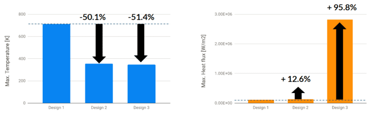
The maximum values of the temperature and heat flux are shown in the table below:
| Design | Configuration | Max temperature (K) | Max heat flux (W/m2) |
| Design 1 | Without heat sink | 712 | 1.18e+05 |
| Design 2 | With heat sink | 355 | 1.35e+05 |
| Design 3 | With heat sink + TIM + heat pipe | 346 | 2.82e+06 |
Potential further design improvements that could be investigated using simulation are, for example, using an aluminum heat sink—which is cheaper and nearly 60% lighter than copper—or different TIMs with varying thicknesses.
It is evident that the selection of appropriate components and materials for the conduction of heat in electronics is one of the key design decisions. Copper, for instance, has a thermal conductivity 1.8 times higher than aluminum. The addition, copper heat pipes can also further increase thermal conductivity, far more than copper heat sinks. At the same time, the choice of aluminum can also be justified, since it is cheaper and lighter, increasing the durability and efficiency of the electronic components.
This is just one example of how thermal simulation can help designers or engineers evaluate their design using simulation. Use the free project template of the case study in this article if you are interested in how additional design changes would impact thermal performance.
SimScale: Thermal Simulation Online
Why aren’t all designers using simulation yet? Several barriers have prevented more widespread adoption of simulation tools by electrical engineers and designers—and here’s how SimScale is aiming to challenge this status quo:
- Accessibility: Traditional software needs to be installed locally on expensive high-performing computers, which just remain idle most of the time. With SimScale, all computations are cloud-based—all that is needed is a web browser.
- Operating costs: Standard commercial simulation software packages are notoriously expensive. With SimScale, there is an option to start simulating right away with a Community Plan.
- Know-how: Most modern tools are designed for experts and experienced simulation engineers. To bridge that knowledge gap, SimScale offers a large public projects library, free training, and live support via chat.
The SimScale Public Projects Library has a wide selection of simulation templates covering various aspects of electronics simulation and heat sink design, including thermal resistance, energy efficiency, cooling management, and heat dissipation.
Despite the significant manufacturing cost reduction of electronic boards and prototype enclosures for devices, it is still a daunting and time-consuming task to analyze the thermal performance of a new design. Download this free case study to learn how the thermal performance of a printed circuit board was investigated with SimScale.

References
- Davis, Sam. ENGINEERING ESSENTIALS-Shrewd Thermal Management Helps Defeat The Heat-Optimization of thermal controls will significantly enhance electronic system reliability. Electronic Design 55.21 (2007): 41-46
- Thermal management (electronics), https://en.wikipedia.org/wiki/Thermal_management_(electronics)