In this article, we discuss methods for adding a topology or a terrain to the CAD model for pedestrian wind comfort simulations.
Terrain
It is common that buildings are present at different heights as they are built on hilly and uneven terrain. If this is true (the buildings do not sit on a perfect 2D plane normal to the Z-axis) then the geometry needs to have the terrain added. This can be done in many ways, either by creating it from map contours or importing the terrain from an online source (such as CADMAPPER).
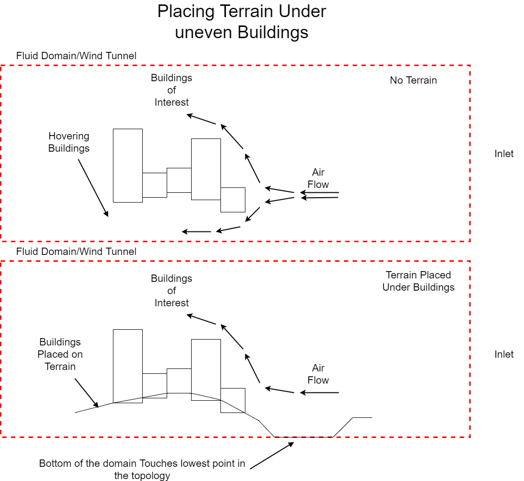
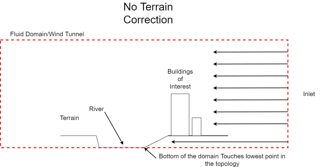
The above illustrations show why the topology needs to be added (to avoid air flowing under the buildings – between them and the wind tunnel floor) and how it should be added. The topology should include the entire base of the building to ensure that there are no caps or thin regions that may skew results.
It is recommended that you thoroughly check to ensure the buildings are not hovering or leaving small gaps between the buildings and the terrain. This is particularly important in the region of interest, as this will lead to high velocities traveling under the buildings, making pedestrian regions appear more uncomfortable than they are, indicating that mitigation is needed when actually it is not.
Terrain Extension
It is common that a region of interest (ROI) is affected significantly by the terrain either inside the region of interest or outside. In this scenario, you may choose to include a terrain (see previous section). By including terrain, you do however bring in an additional question, and that is how the terrain sits in your virtual wind tunnel. Below are a few options, and there are advantages and disadvantages to each.
By having a wind tunnel larger than the provided terrain we expect some amount of fluid to travel ‘under’ the terrain. This will do a few things, velocities above the terrain tend to be higher, as the reference point for the wind profile will start at the ground level at the inlet, which is below the actual terrain level. Additionally, the domain will have more cells that are refined and will take longer to compute. Furthermore, if any caps in the terrain are present, you risk a large amount of flow going above the terrain from below. Generally speaking, this is considered the worst method of dealing with topology.
The ground extension involves moving the boundaries from the edge of the topology to beyond the extent of the simulated domain. The advantage here is similar to the turntable option, fluid is not expected to flow under or out of the topology providing the fluid domain intersects the geometry for every direction in both cartesian terms, but also in compass terms.
In situations where the boundaries of the initial terrain surface are not ending at the same height for each direction, it is best practice to extend the ground radially to a common reference height, but this is not necessary.
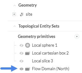
A question here arises, how do we know when the terrain is extended far enough? The answer is within the SimScale platform itself. Simply upload the geometry as it is and place the ROI, and visualize the extent of the simulated region, by activating the “Flow Domain (North)” in the scene tree at the right side of the viewer region.
The pink box is the visualization of the virtual wind tunnel for the example of the northerly wind direction. The green cylinder around it highlights the minimum extent of the terrain.
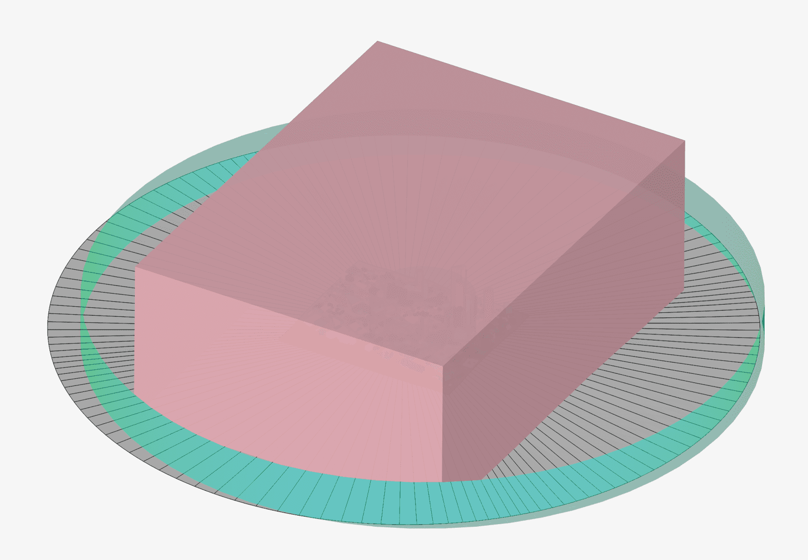
The above image shows how the domain is extended past the green circle (mostly), this finishes off a well-defined geometry for simulation purposes.


