Imprint is a CAD operation that helps to recognize solid/solid and solid/fluid interfaces. Later on, these interfaces will be assigned as contacts in Conjugate Heat Transfer (CHT) or Finite Element Analysis. The contact definition is vital since these regions are responsible for transferring heat and loads between parts.
By performing the imprint, shared faces between neighboring parts are recognized and embedded into the geometry, ensuring that the solver can accurately detect and interpret these physical boundaries.
Imprint Operation
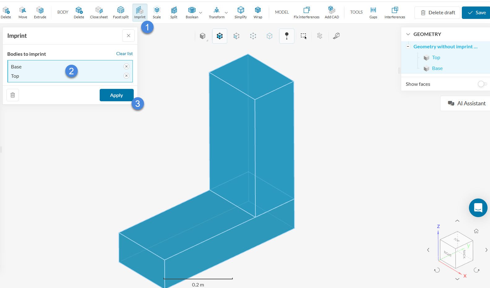
Before going through the effect of imprinting a geometry, let’s first see how to perform this operation in SimScale. The imprint operation can be run within the CAD editing environment:
In CAD mode, follow the steps to perform the imprint operation on selected geometries:
- Select the ‘Imprint’ operation
- Select the parts that need to be imprinted from the viewer or the geometry tree
- Run the operation by clicking ‘Apply’
Did you know?
To quickly select all parts, you can use the box selection tool. You can either select this from the selection menu or by holding the ‘b’ key on your keyboard. You can find more tips and tricks about the selection tools here.
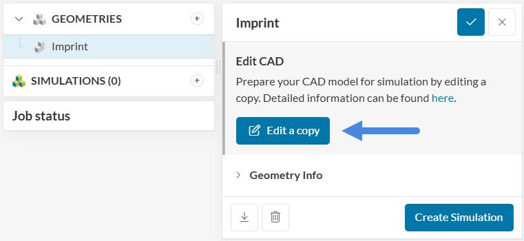
After running the operation, you can click on Save as copy in the top-right corner to export the updated CAD model to the Workbench.
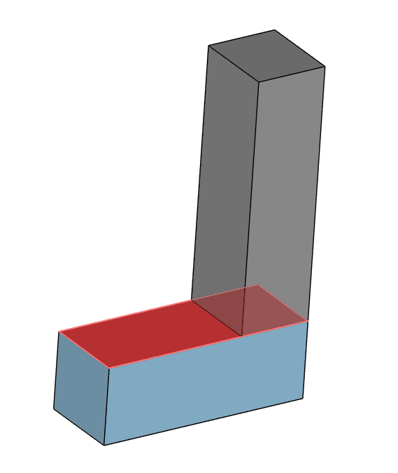
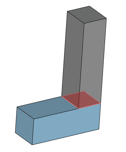
Now that we know how to imprint a model, let’s see what it does to the geometry. The following picture represents an assembly, which consists of two solid parts that touch.
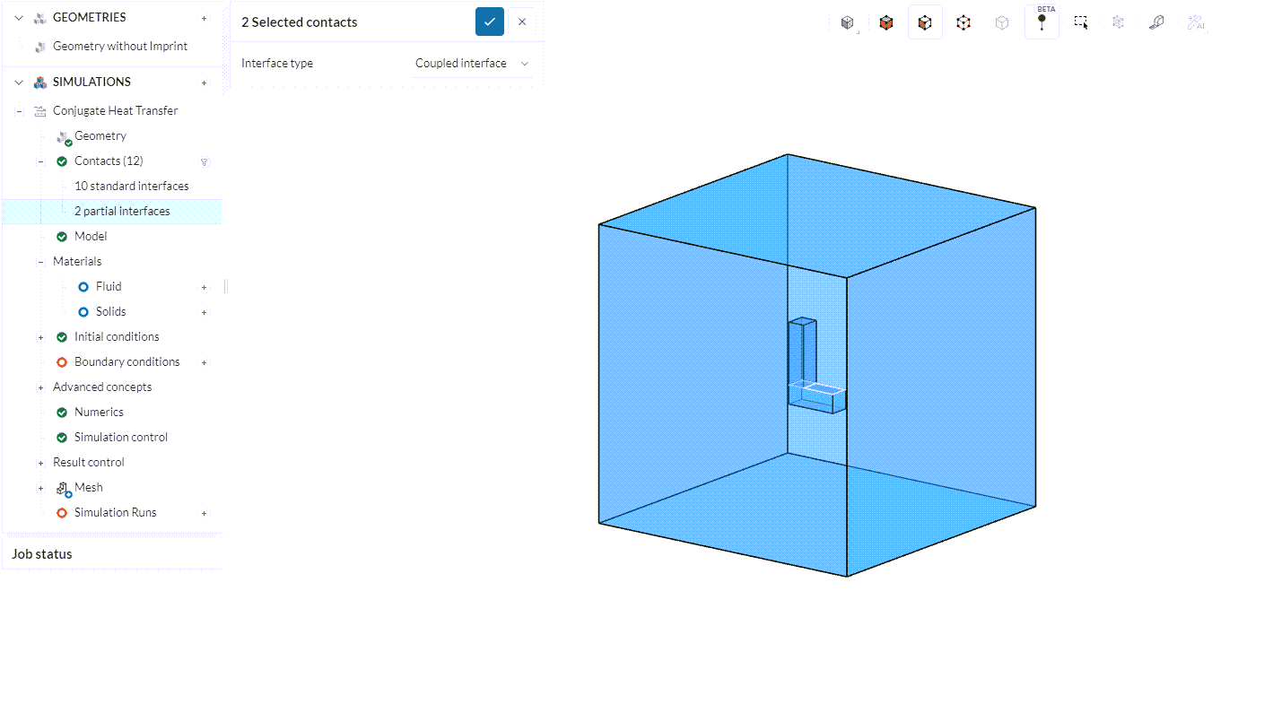
Without an imprint operation, the interface between the solid bodies may not be correctly recognized and grouped as partial interfaces. This will be the case, for example, if we have an enclosure enveloping the two parts.
In Figure 4, the highlighted face (red face as shown in Figure 3) shares contact with both an air domain and a solid body. It is recognized as “2 partial interfaces” in the simulation tree. To prevent partial contact, the face should be split into two interfaces, one between the solid part, and the other between the air domain.
The imprint operation does exactly that – it splits the surfaces so that we can have precise contact detection. Comparing the highlighted face from Figure 3, we can see that it now has been split in two, due to the imprint operation:
In this case, we can obtain valid contacts in the simulation setup.
Note
If none of the above suggestions solved your problem, then please post the issue on our forum or contact us.