
American Wind used CFD with SimScale to optimize its micro wind turbine.

Times faster
simulation

Average savings on
hardware

Operating conditions
tested
Times faster
simulation
Average savings on
hardware
Operating conditions
tested
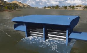
The company behind the market’s top micro wind turbine, American Wind, developed their innovative design using computational fluid dynamics (CFD). Instead of big turbines that are located farther away from their intended power use, American Wind’s products brings the power generation to where it is used.
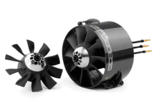
Never before has a 1-kilowatt generator been squeezed into a device just 3 inches in diameter. That is until American Wind developed its innovative micro wind turbine, which is integrated with a small, yet very powerful, generator. Still, a powerful generator doesn’t mean much in a wind turbine if it’s not able to capture the energy from the wind. This is why the company developed a new blade design to replace the simple airfoil-based ones. For this, American Wind’s founder Robert Yost used his experience in designing jet engine turbines to develop a blade that used both airfoil technology and jet turbine technology. This allowed American Wind’s turbines to start functioning at a much lower wind speed than any other turbine on the market, which means that the micro wind turbine can create power through a larger range of wind speeds.

With the design ready, Robert wanted to investigate the performance of the MicroCube wind turbine under operational conditions. The verification of the experimental results would be the first step before using the analysis for further development. It was clear that experimental tests provided the most accurate data, but they also gave a limited overview of the micro turbine’s performance. Using computer-aided engineering with SimScale, it was possible to visualize all the features of the wind flow at any given point. Having such data provided a significant advantage for optimizing the product’s design.
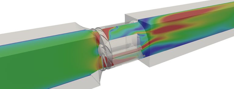
The MicroCube CAD model was meshed in a way that resembled a live wind tunnel at which it was tested. A square channel was placed before and after the compact MicroCube. The expected air flow was turbulent, though the range of operation wind speeds indicated that an incompressible model would be sufficient.
To incorporate the motion of the fan blades, a Multiple Reference Frame (MRF) rotation model was used. Although the MRF model simplifies the simulation by “freezing” the rotor, it allows for a fast and accurate evaluation of steady-state conditions of the case. The obtained mesh consisted of over 7 million volumes. It included local area refinements, surface refinements, and a turbulent boundary layer.
During the analysis, it was assumed that the blades were rotating at a fixed speed dependent on the inflow air velocity, based on experimental data. This is a common approach when testing turbines, which allows for the investigation of actual wind flow patterns. The captured data involved all flow field data (pressure, velocity) and extra forces and moments acting on the whole MicroCube. During post-processing, the difference in flow rotation before and after the turbine was calculated.
Being cloud-based, SimScale enabled the engineers to run multiple simulations at the same time. Thanks to that, the whole analysis was done over 20 times faster compared to what would be required on a single computing unit.
In total, 26 operating conditions were analyzed, ranging from extremely low wind speeds up to the expected limit conditions. On average, each simulation required 10 hours of computation time. Four of these simulation runs needed to be repeated with modified numerical conditions and extended convergence times to obtain correct results.
An interesting result found during the analysis was the occurrence of a wind recirculation region attached to the stator arms of the MicroCube. Being aware of the presence of this flow feature opens the possibility for optimizing the shape of the stator (generator mount) in a way that will reduce energy losses due to recirculation.
In total, 26 operation conditions were analyzed with the SimScale cloud-based platform.

Subscribe to our newsletter
By subscribing you agree to with our Privacy Policy
Product
Solutions
Resources
Sign up for SimScale
and start simulating now