Tutorial 1: Stress Analysis of a Bracket
In this tutorial, you will learn to quickly set up a basic structural simulation of a bracket and conduct stress analysis using SimScale.
The tutorial project “Tutorial 1: Structural Analysis of a Bracket” has been imported and is open in your SimScale Workbench.
1. Select the Analysis Type and Create Simulation
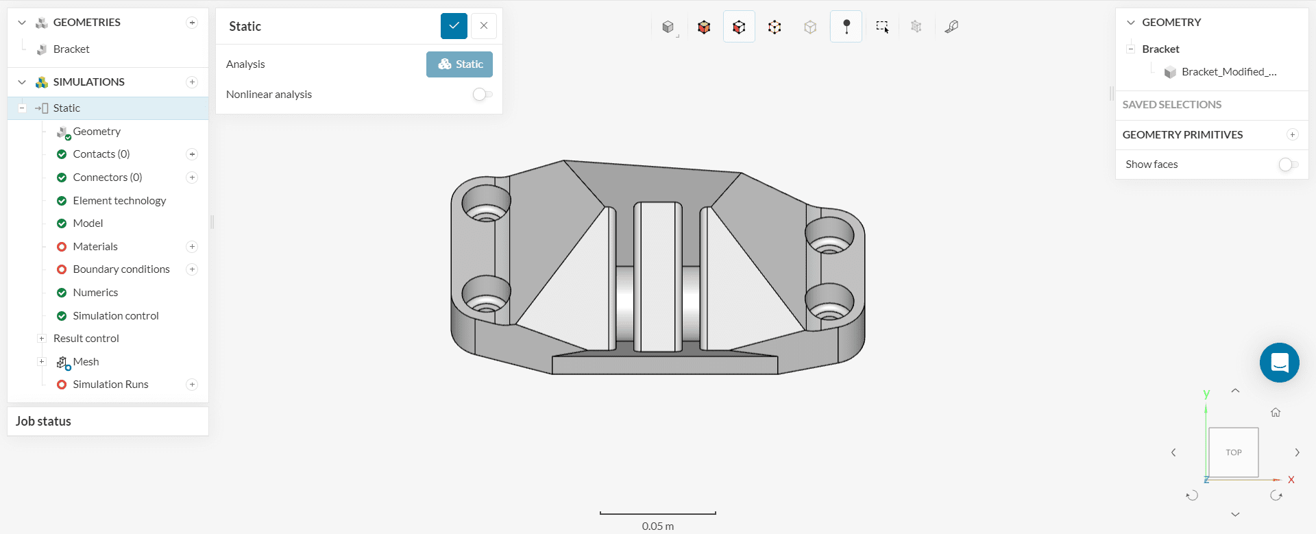
Figure 2 demonstrates the current layout of your screen. This is the Workbench and the geometry is ready for the simulation.
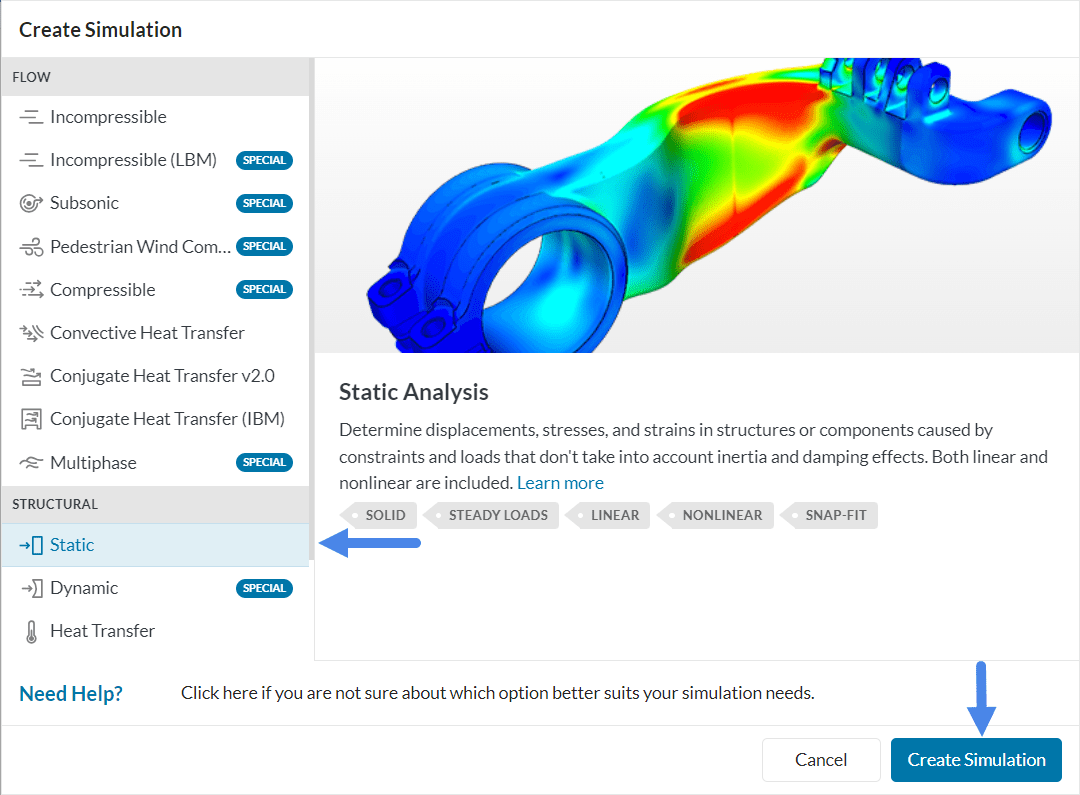
To create a new simulation, click on the ‘Create Simulation’ button.

This will open up the Analysis type library. Select ‘Static’ as the analysis type and click ‘Create Simulation’.
A new simulation tree will automatically be generated on the left side of your Workbench, containing all parameters and settings required to start the simulation.
2. Set Up the Simulation
A successful simulation setup means a complete and accurate definition of the physics defined within the simulation tree. We need to define the following settings:
- Material of the bracket
- Boundary conditions acting on the bracket
2.1 Define a Material
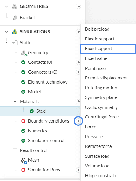
To assign a material to your model, click on the ‘+’ button next to Materials in the simulation tree.
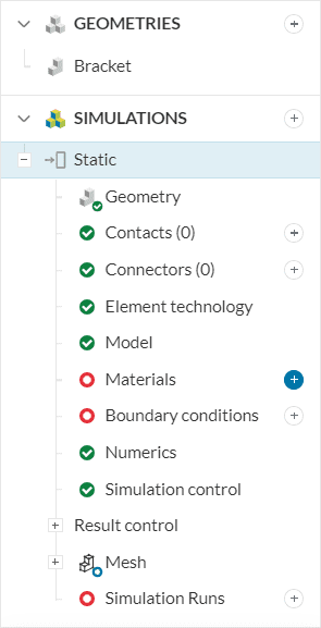
The Material library will open containing pre-defined materials. Scroll down to select ‘Steel’ and click ‘Apply’.
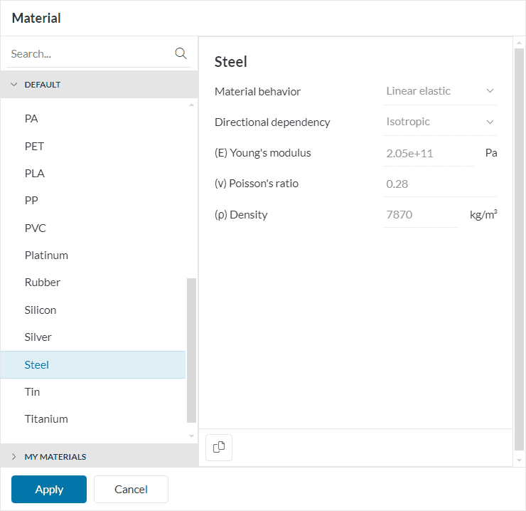
The material will automatically be assigned to the bracket.
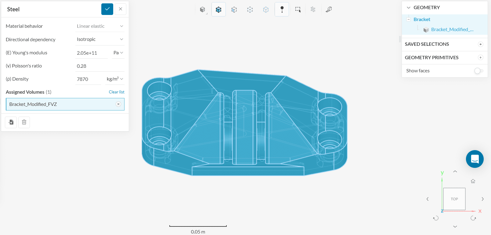
Note
The color blue indicates that the material has been assigned.
2.2 Boundary Conditions
Two boundary conditions, fixed support and force, need to be assigned to the bracket.
A. Fixed Support
To create a new boundary condition, click on ‘+’ next to Boundary conditions in the simulation tree. Select ‘Fixed support’ from the list.
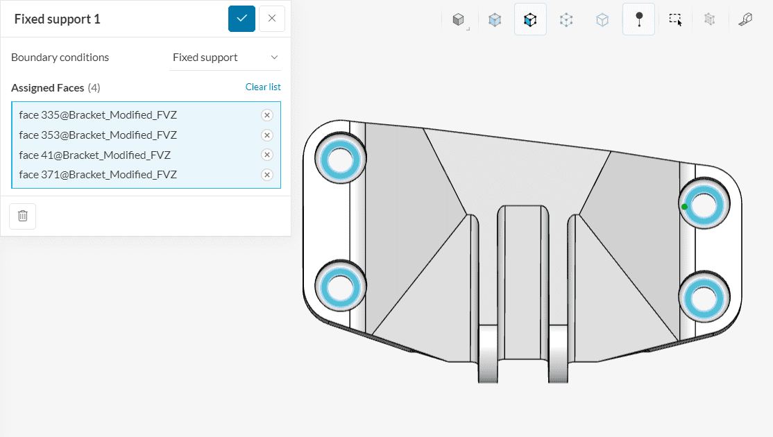
After that, a dialog box for the fixed support boundary condition will appear. Assign 4 faces subjected to a fixed support as shown below:
B. Force
Repeat the process and add another boundary condition by hitting the ‘+’ button next to Boundary conditions. Select ‘Force’.
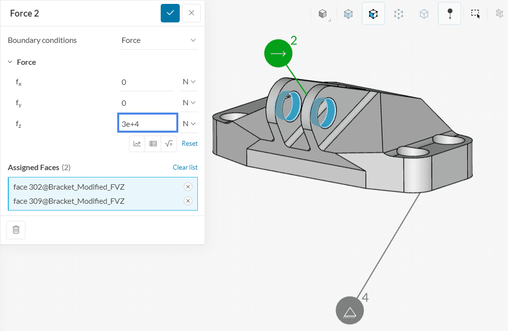
We will define our force to be ‘30000’ \(N\) in the z-direction and assign it to two faces as shown in Figure 10.
3. Mesh
To create the mesh, we will use the standard algorithm, which is automated and delivers good results for most geometries.
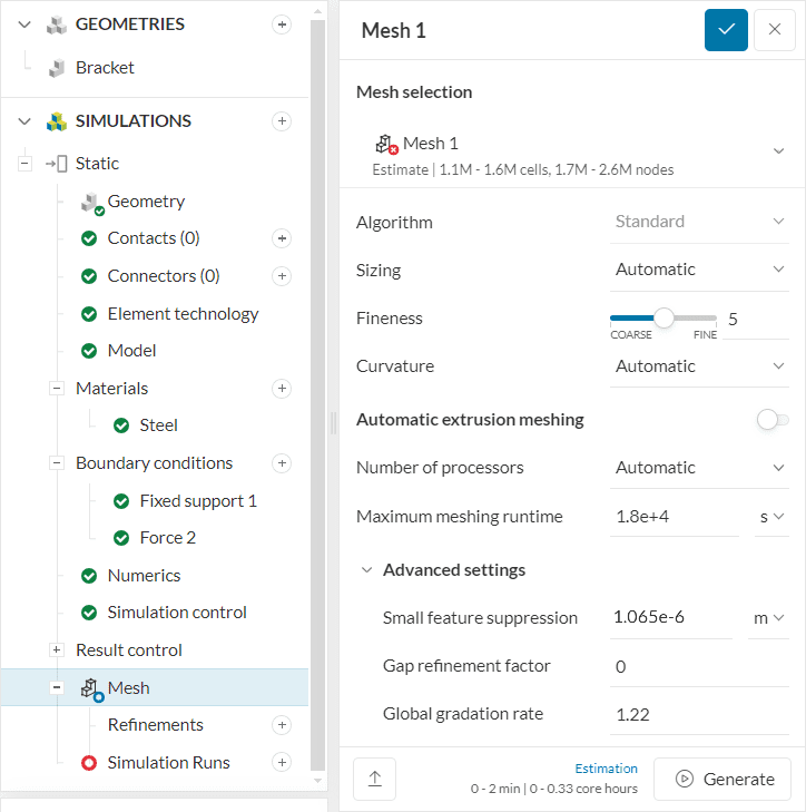
No changes in the default settings are needed. For linear static simulations, SimScale creates 2nd order meshes by default, which increases the accuracy of the analysis.
4. Start the Simulation
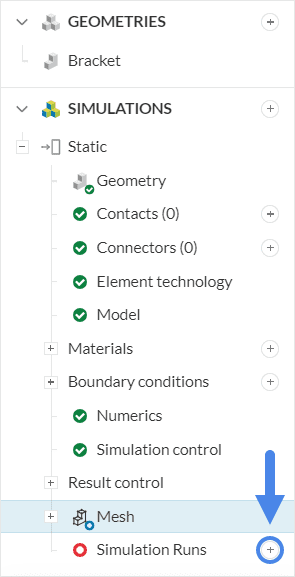
Now you are ready to start your simulation run. The mesh will be automatically generated as the first step in the simulation run and therefore is not required to be generated separately. Click on the ‘+’ button next to Simulation Runs.
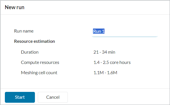
At this point, you will be shown a dialog box containing an estimate of the computing resources that will be spent to run your simulation. Proceed by pressing ‘Start’.
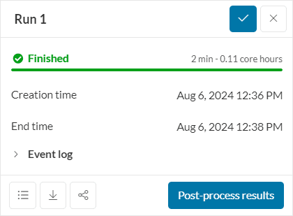
Once the simulation run is finished, the status will be changed to Finished in the run settings panel.
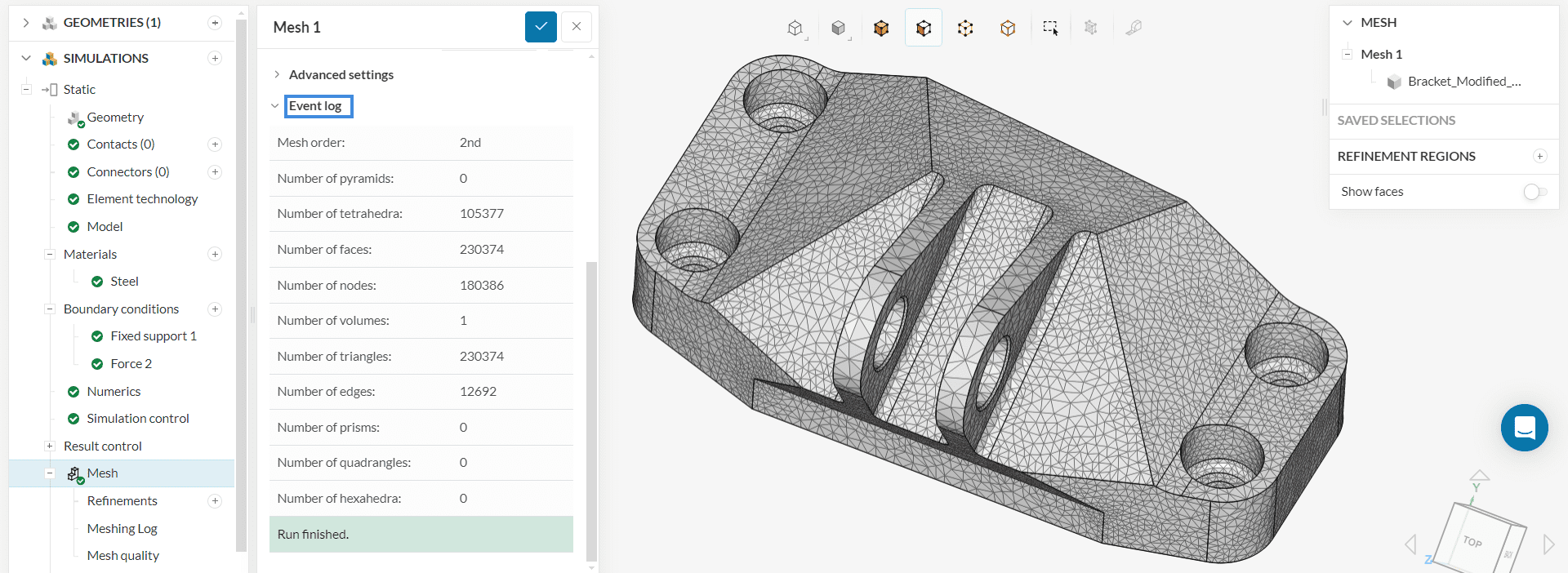
4.1 View the Mesh
The generated mesh can be viewed under Mesh. Additional details related to the mesh cell characteristics can be inspected under the Event log. The mesh consists of second-order tetrahedral cells.
5. Post-Processing
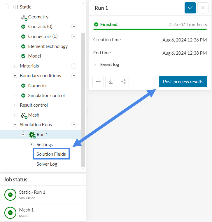
To access the post-processor click ‘Post-process results’ or ‘Solution fields’ under your run to load the results in the Post-processor.
When directed to the post-processor, you can start analyzing your results. SimScale’s integrated post-processor consists of filters and different viewing tools to better visualize and download the simulation results. For this tutorial, we will show the von Mises stress and the deformations in the bracket.
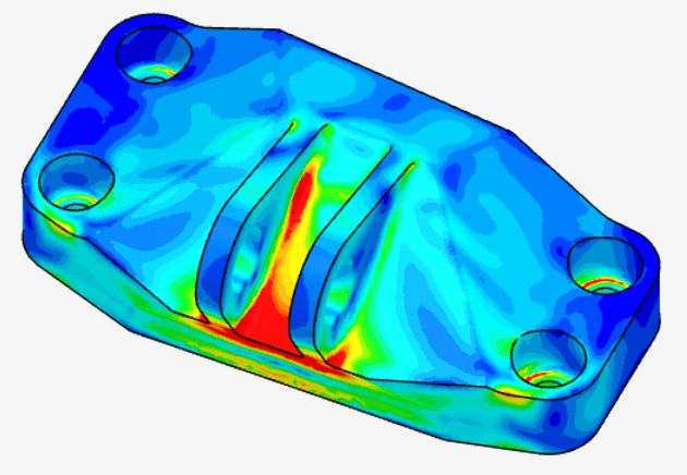
To analyze the von Mises stress on the bracket structure, make sure that ‘Von Mises Stress’ is defined under Parts Color:
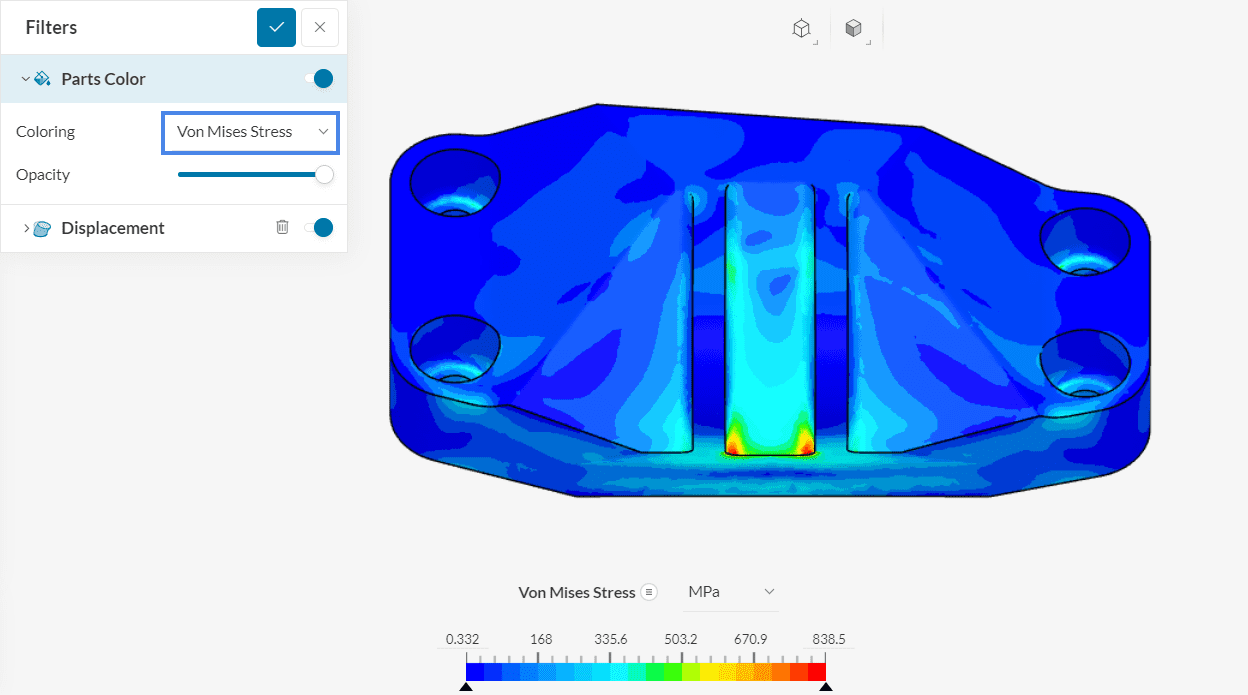
It can be seen that the highest stress levels occur near the edge end of the bracket, where the force boundary condition is applied.
Since deformation is also important in stress analysis, we can visualize both the von Mises stress and displacement at the same time. The displacement settings can be changed under the Displacement filter:
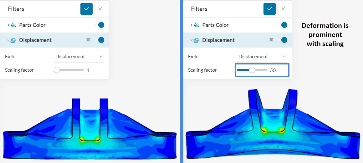
Since the displacements in the bracket are tiny, it’s possible to scale them up to obtain a better visualization. In the image above, the displacements have a Scaling factor of ’50’. As expected, the free end of the bracket undergoes the largest deformations, with respect to the initial position.
Now, to see the actual displacement values, we can also adjust the Parts Color to ‘Displacement Magnitude’:
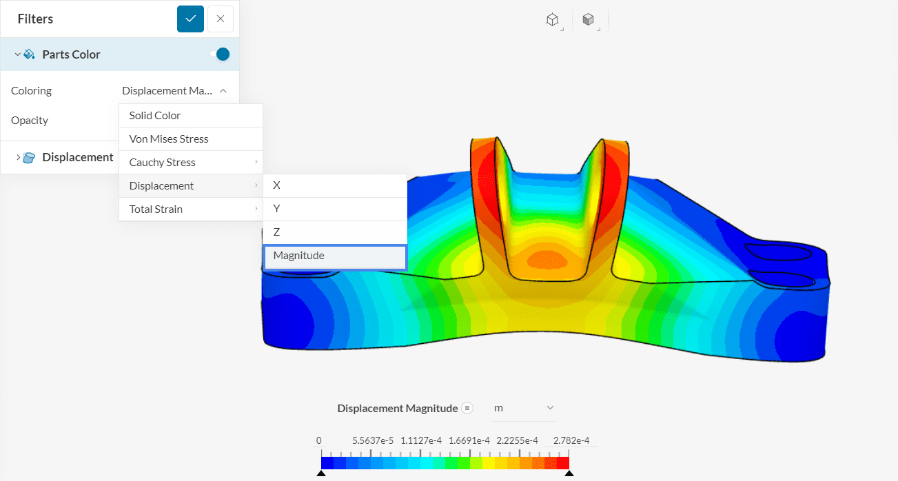
The total maximum displacement due to the weight of the structure and the applied force is roughly 0.3 millimeters in this scenario.
Congratulations! You just finished your first Stress Analysis simulation on SimScale!
Find more tutorials on our website: SimScale Tutorials and User Guide