Tutorial 1: Stress analysis of a Connecting Rod
In this tutorial, you will learn to quickly set up a basic structural simulation of a connecting rod and conduct stress analysis using SimScale.
The tutorial project “Tutorial 1: Connecting rod stress analysis” has been imported and is open in your SimScale Workbench.
1. Select the Analysis Type and Create Simulation
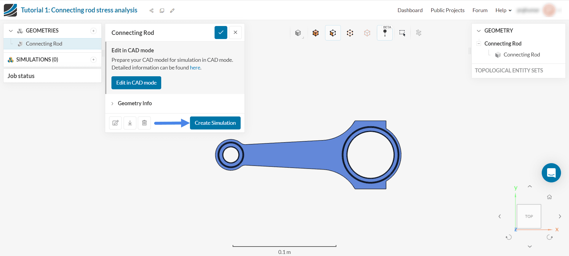
Figure 2 demonstrates the current layout of your screen. This is the Workbench and the geometry is ready for the simulation.
To create a new simulation, click on the ‘Create Simulation’ button.
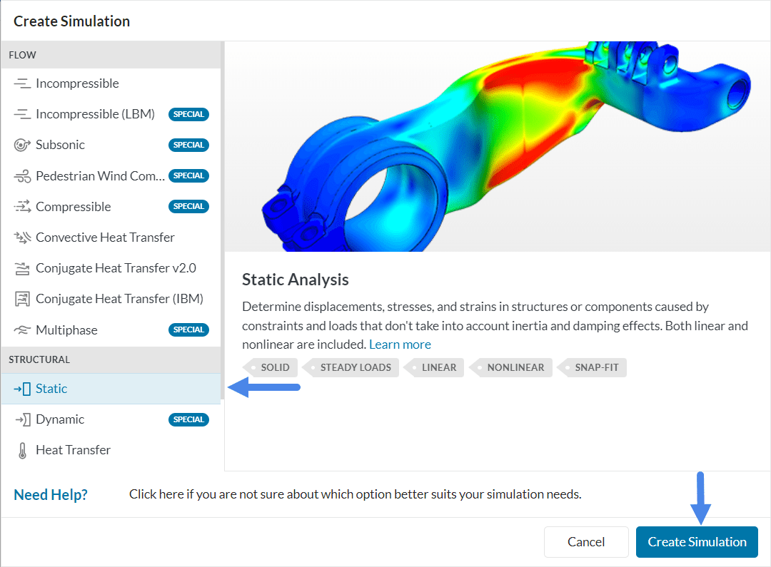
This will open up the Analysis type library. Select ‘Static’ as the analysis type and click ‘Create Simulation’.
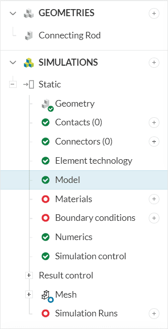
A new Simulation tree will automatically be generated on the left side of your Workbench, containing all parameters and settings required to start the simulation.
2. Set Up the Simulation
A successful simulation setup means a complete and accurate definition of the physics defined within the simulation tree.
2.1 Model
To define and modify the direction of gravity, click on ‘Model’.
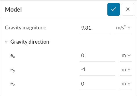
This will open up the settings panel for Model. In this case, gravity is acting in the negative y-direction. Add ‘9.81’ m/s as the magnitude and ey as ‘-1’ to indicate gravity in the negative-y direction.
2.2 Material
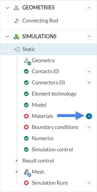
To assign a material to your model, click on the ‘+’ button next to Materials in the simulation tree.
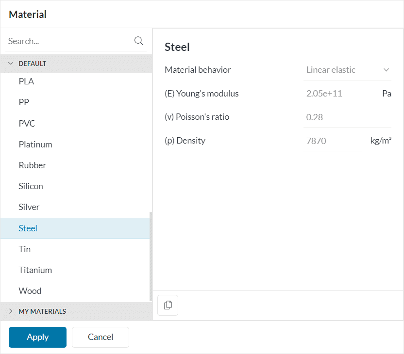
The Material library will open containing pre-defined materials. Scroll down to select ‘Steel’ and click ‘Apply’.
The material will automatically be assigned to the connecting rod.
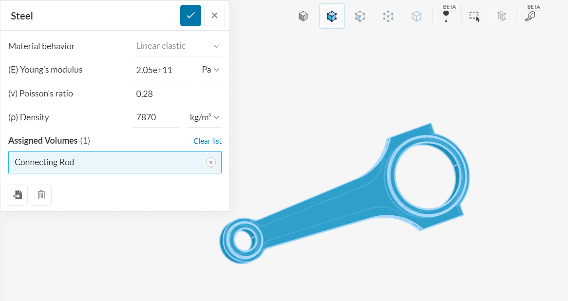
Note
The color blue indicates that the material has been assigned.
2.3 Boundary Conditions
Two boundary conditions, pressure (load) and fixed support, need to be assigned to the connecting rod.
A. Pressure
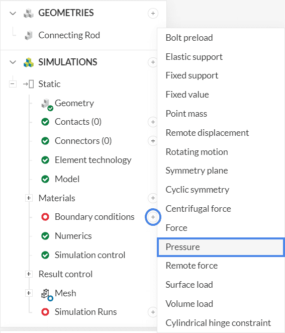
To create a new boundary condition, click on the ‘+’ button next to Boundary conditions in the simulation tree. Select ‘Pressure’ from the list.
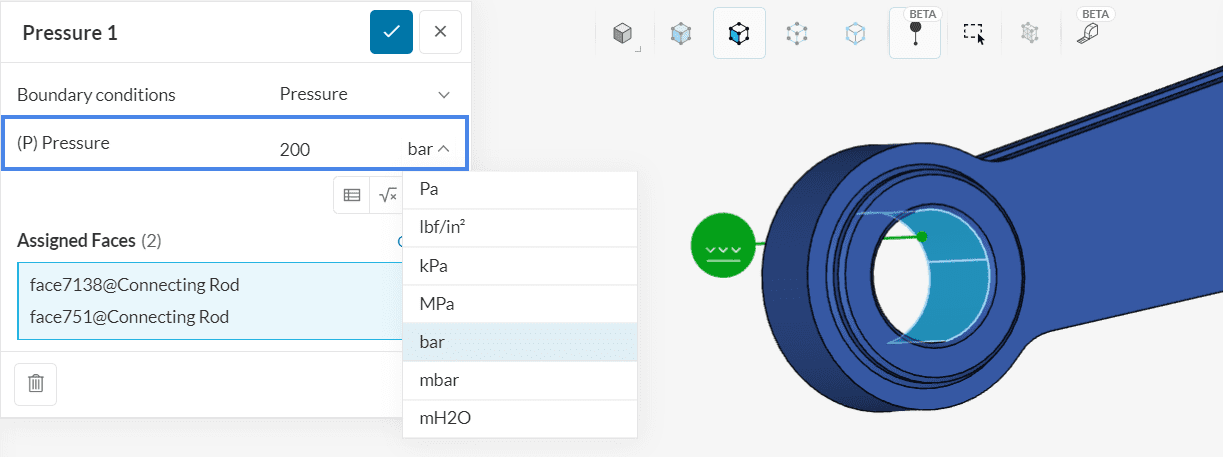
Set the pressure value to ‘200’ bar. You can change the units from the dropdown by selecting ‘bar’ as the unit of pressure. (see Figure 10)
Now select the faces on which the pressure should act. In the viewer, select the two inner faces inside the smaller opening of the rod.
Note
The color turns blue, indicating that they will be assigned to the current boundary condition.
B. Fixed Support
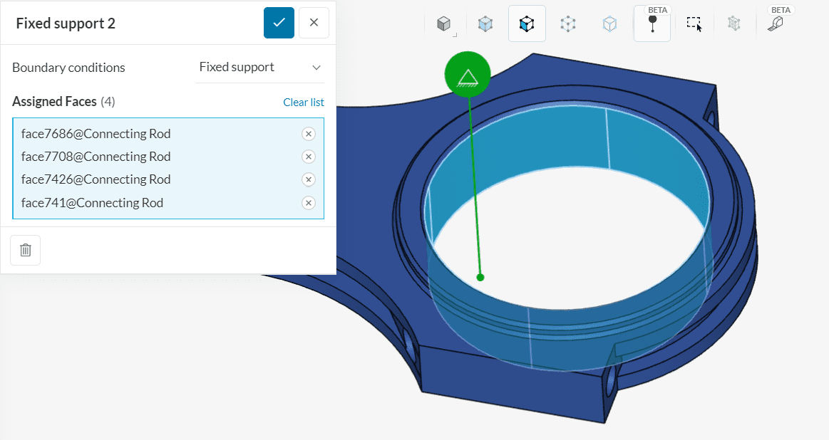
Repeat the process and add another boundary condition by clicking on the ‘+’ button next to Boundary conditions. Select ‘Fixed Support’. Assign all the inner faces at the larger end of the connecting rod in the viewer.
3. Start the Simulation
Now you are ready to start your simulation run.
The Numerics, Simulation Control and Mesh settings are set by default and do not have to be changed for this simulation.
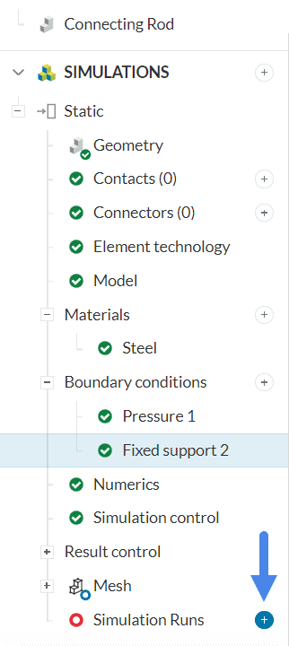
Create a simulation run by clicking on the ‘+’ button next to Simulation Runs in the simulation tree.
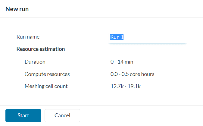
A dialog box will appear stating the estimated amount of resource consumption. Click ‘Start’ in the New run dialog box to start the simulation run.
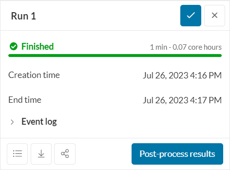
Once the simulation run is finished, the status will be changed to Finished in the run settings panel.
4. Post-Processing
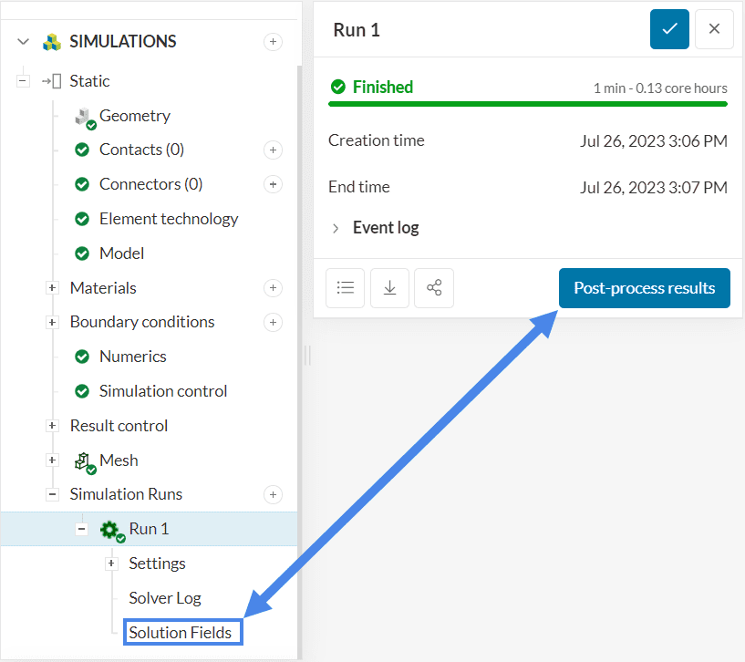
To access the post-processor you can click ‘Post-process results’ or ‘Solution fields’ under your run to load the results in the Post-processor.
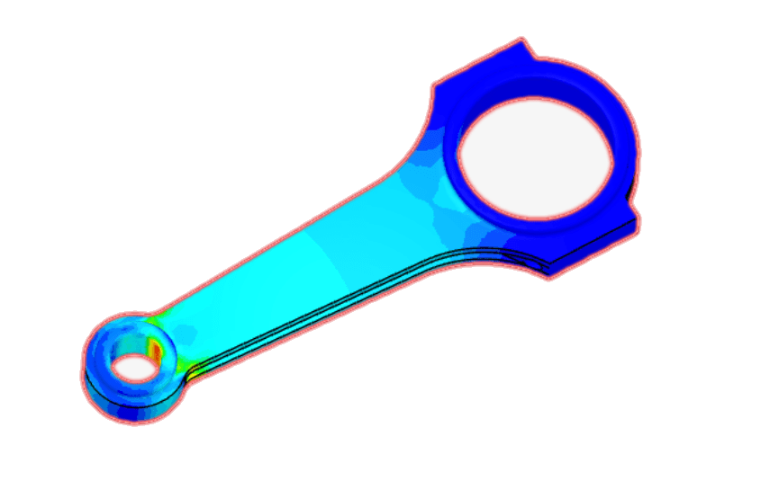
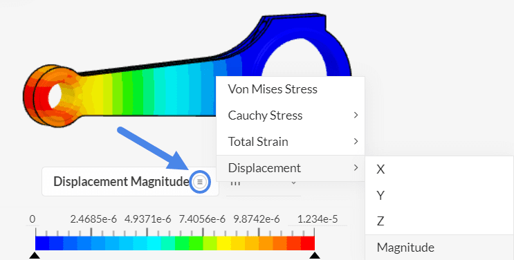
SimScale’s integrated post-processor consists of filters and different viewing tools to better visualize and download the simulation results. Figure 16 shows the default view where the displacement field is applied with contours of Von Mises Stress for visualization.
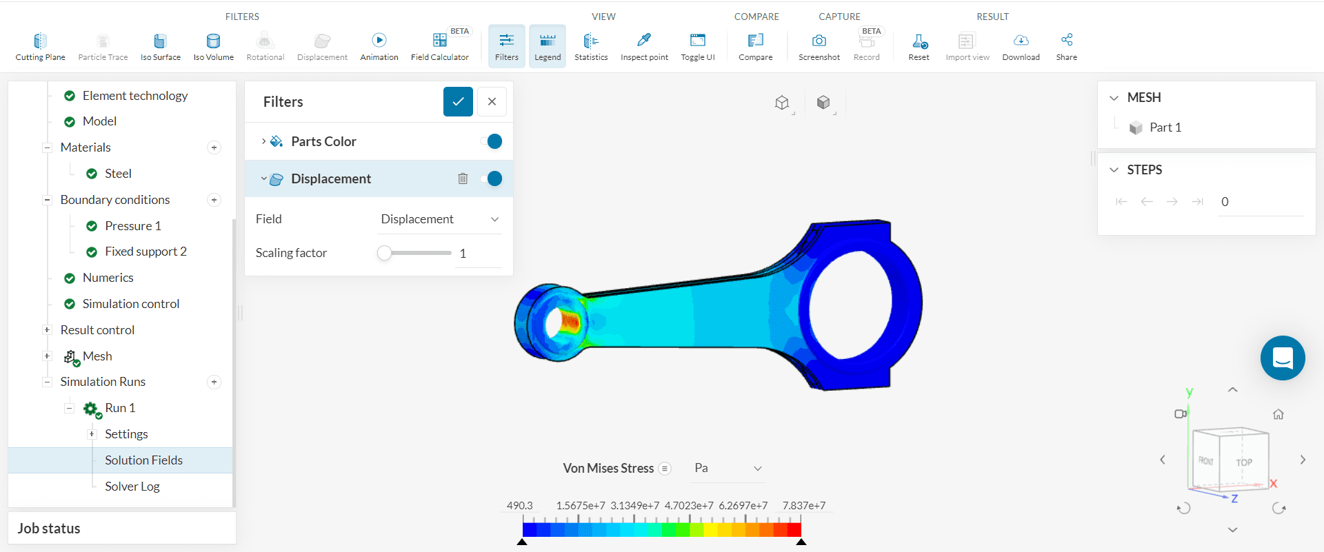
Regions of high stress load are colored red while lower stress regions are shown in blue.
The legend can be changed to some other quantity of interest as shown below:
Congratulations! You just finished your first Stress Analysis simulation on SimScale!
Find more tutorials on our website: SimScale Tutorials and User Guide