TechSAT Uses Cloud-Native Structural Analysis to Optimize Airborne Electrical Equipment

€15K savings on licensing and hardware
€15K savings on licensing and hardware
TechSAT is a company that provides solutions for the aerospace industry, supporting aircraft systems development, integration, testing, and maintenance with state-of-the-art equipment and services. TechSAT uses simulation as a critical component within its design and engineering process to optimize and validate product performance. TechSAT – solutions for the aerospace industry, VTOL, designing and adding new products. Since 1986 TechSAT GmbH has been a reliable and competent partner in the aerospace industry, supporting aircraft systems development, integration, testing, and maintenance with state-of-the-art equipment and services. TechSAT’s core competence is the design and development of test systems for integrating, verifying, and validating aircraft systems, including related consulting and services.
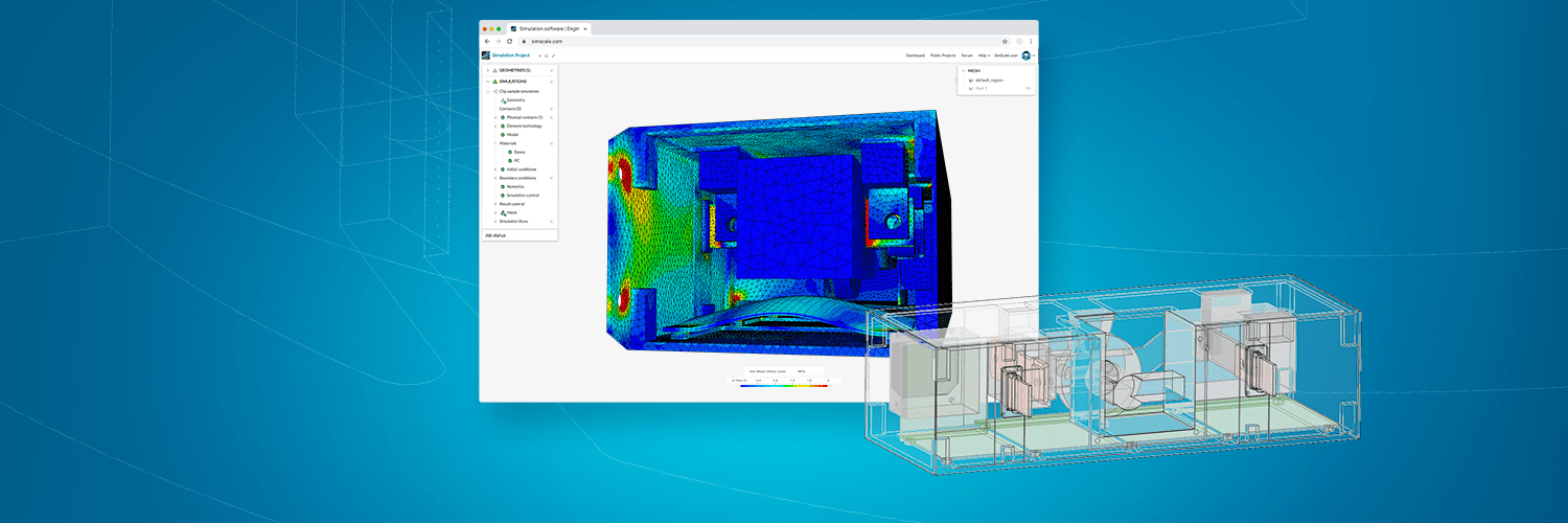
Mar Sanchez, a mechanical engineer at TechSAT is part of the engineering design team looking at new components and products for innovative and safe designs. Physical prototyping in the aerospace industry is a very costly and heavily regulated activity with significant amounts of physical testing required to satisfy strict standards. TechSAT uses simulation at an early stage of the product development process to evaluate their designs’ structural and thermal aspects. Examples include frequency and harmonic analysis on structural fixings and heat transfer studies on integrated electronics for heat dissipation. In this case study, we show how TechSAT leverages FEA, focused on vibration, to verify upfront the best CAD geometries and fixation methods for their aircraft components. This is achieved using the SimScale frequency and harmonic analysis simulation workflow. Vibration analysis at this early stage can assist in disqualifying inferior designs earlier by modeling the natural frequencies which are used to identify excitation modes that might be dangerous. Furthermore, harmonic analysis simulates vibration at specified conditions and predicts physical displacements and stresses.
The live support through the SimScale platform has been especially helpful to meet our project deadlines. The additional learning resources provided by SimScale including the knowledge base and documentation is simple to use and help us to quickly figure out what to do.

Mar Sanchez
Mechanical Engineer at TechSAT
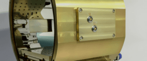
An early concept development for an airborne electronics housing unit is subjected to vibrations, physical shocks, and impacts during flight operations. Its survivability is critical in overall flight safety and performance and subject to many standards, such as the RTCA DO 160G – Environmental Conditions and Test Procedures for Airborne Equipment, which provides standard procedures and environmental test criteria for testing airborne equipment for the entire spectrum of aircraft from light general aviation aircraft and helicopters through the “jumbo jets” and SST categories of aircraft. Section 8 refers to vibration with tests to demonstrate that the equipment complies with the applicable equipment performance standards (including durability requirements) when subjected to vibration levels specified for the appropriate installation.
One critical concern for survivability is the vibration of the system during operation. The unit must be certified under DO-160G, which stipulates that the unit must survive specific excitations between 10 and 2000 Hz. Rather than full DO-160G test replication, a few worst-case scenarios can be simulated at the conceptual phase to understand the best design approaches before adding detail. In this early concept study, TechSAT simulated the natural frequency-induced modes of interest and excited those with a worst-case scenario of 10g acceleration to predict component structural limits. This would then show them how much physical displacement or deflection might be in the PCB contained within the electronics housing. Using this insight, they could then confidently place various PCB chips and components on the board where appropriate, and it would inform their soldering/fixing strategy. For example, larger chips and PCB components with higher inertia need stronger bonding to withstand vibrations. They should also not be placed in areas of high deflection or excessive vibration amplitude.
A simplified model imported into SimScale from Fusion360 is analyzed, including only the significant components and PCB board, as these parts will dominate the system vibration. The study focuses on the extent of vibration of the PCB board. Deflection of the board during vibration must be minimized and understood in detail to allow optimal placement of the complex electronics components to ensure structural integrity. Larger pieces should be placed where the slightest deflection is expected to avoid solder attachment failure due to the inertia of the component during vibration.
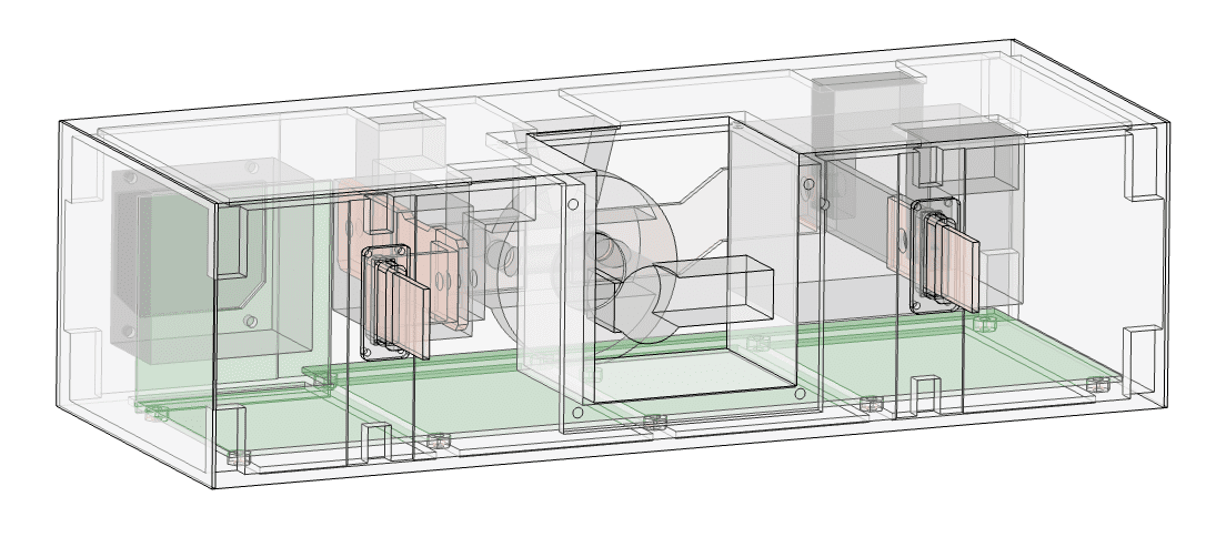
One key question for TechSAT is how the unit should be supported by the airframe. Two options are considered in this case; a fixed contact boundary condition with some pinned support on the side for bolted flanges and a fixed rack that provides support on all sides. For the two support concepts TechSAT wanted to:
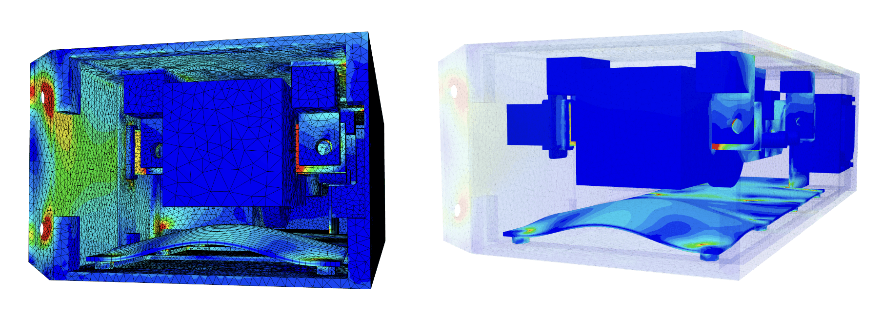
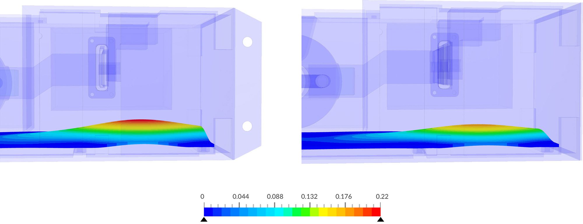
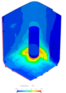
The SimScale platform has automated meshing during the simulation set-up phase and generated a second-order element mesh with tetrahedral cells. The appropriate materials were selected from the materials library (linear materials for frequency analysis). With complete 3D post-processing and simple plots and summary data, TechSAT could see plots for all modes, 46 eigenfrequencies within the specified range, and plot modal mass to see how much dynamic response is due to modal impacts. The first mode is easiest to excite and therefore considered dangerous, and the results showed the effect of this first mode on the product. The whole model was excited at 10g at its fixing points in the next step using harmonic analysis with a global damping ratio of 5%. We could see a 3D solution filed to animate the total displacements, in this case, about 0.2 mm in the specified direction.
From the two types of fixing, we learned that in the full rack support (Case 2) there is 18% less deflection in the PCB board. Specifically, the maximum shape distortion occurred on the right-hand side of the PCB board, suggesting an additional fixing might be best placed there. For both designs, the maximum deflection occurs at the same point on the right-hand side of the board therefore when considering the resonance of this particular eigenmode it is important to avoid placing large components on the far right-hand side of the board. Larger components would shake more because of their higher inertia.
After inspecting all-natural frequencies of concern for the PCB within the DO-160G testing range, TechSAT understood the worst-case board deflections during simulated vibrations. This means that the engineers can now select an evidence-based fixation approach, position the electronic components appropriately, avoid excessive shaking during vibrations, and have the insight to predict product survivability in the prototyping and real-world use cases.
Amongst the many benefits of using SimScale has been the reduced need for physical prototyping, saving time, and cost. TechSAT can now arrive at a smaller number of competing final design options and focus the more elaborate physical testing to strict standards on a few pre-qualified design candidates. Overall this has reduced our time to develop products and get them to our customers, and the cumulative impact of these benefits over time will be significant.
TechSAT also uses simulation for mechanical shock testing using dynamic analysis following DO-160G and the cooling performance of thermal shocks using transient heat transfer analyses. Extending the use of SimScale, TechSAT will conduct virtual testing of detailed design candidates for certification and include a more advanced simulation setup to calibrate their strict physical testing criteria to a simulated version.
After evaluating several tools, we found SimScale to be fast and easy to use as well as being cheaper compared to others with the same capabilities. We saved over €15K in licensing and hardware costs by opting for the fully cloud-native solution by SimScale.
Mar Sanchez
Mechanical Engineer at TechSAT


Subscribe to our newsletter
By subscribing you agree to with our Privacy Policy
Product
Solutions
Resources
Sign up for SimScale
and start simulating now


