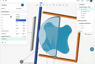
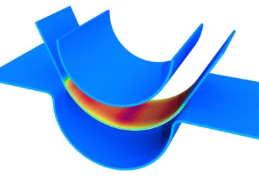
In 2016, I published one of my very first articles titled “How to Choose a Hyperelastic Material Model for FEA”, and almost 2.5 years later, I’ve comes back to address the persisting issue of hyperplastic materials/polymers in a different light. Today, let’s see how this is related to the Space Shuttle Challenger (OV-99). Rubber sealing is used across all industries, in most applications and almost taken for granted today. Here is an interesting simulation from the SimScale Public Projects Library: rubber seal sliding.
If only this was considered three decades ago, it could have saved the Space Shuttle Challenger from disaster. There are numerous articles addressing the Challenger disaster in the media, from Wikipedia pages to coverage on the National Geographic. This page on NASA website lists some of the major theories and reports on the tragedy.
One of the cruelest aspects of the catastrophe was the deadly fate of the crew who were on-board the Space Shuttle Challenger. It was originally believed that the shuttle exploded, and the crew died instantly. Later, it was found that the astronauts were alive, trapped in their seats and even conscious until the crew cabin hit the Atlantic Ocean at 321 kilometers per hour…
Could the Challenger disaster have been prevented if the engineering was executed better?
Sign up and check out our SimScale blog for much more!

What Was the Challenger Disaster?
The Space Shuttle Challenger, with a seven-member crew was launched on the morning of 28th January 1986 from Cape Canaveral, Florida (USA). The original launch for the 27th was postponed. The temperature on that day was about -7 °C. This was the 10th flight of the Space Shuttle Challenger.
73 seconds into the flight, it was believed that the solid boosters exploded killing all the crew on-board and plunging the shuttle into the Atlantic Ocean. Initial investigations reported that the O-ring between the solid boosters failed due to the low temperatures on that day, eventually leading to the breakage of the shuttle.
However, over the last 30 years, this has been a major case study for engineers and academics alike who have questioned the theories rigorously. Today, our understanding of the matter has greatly developed and matured as technological advancements revealed the true causation of the Challenger disaster.
What Actually Happened to the Space Shuttle Challenger?
As I discussed in a previous article on hyperelasticity, rubber materials demonstrate a glass transition behavior. This means that at temperatures that surpass this glass transition temperature, materials are extremely rubbery. In contrast, temperatures below this cause materials to behave in a glassy and brittle manner.
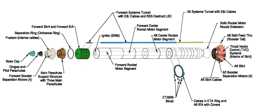
These O-rings were installed between the solid fuel segments as shown in Fig. 01. Their purpose was to prevent hot combustion gases and particles from escaping the inside of the booster. For redundancy, two O-rings were installed. On the internal layer, a heat-resistant putty was added to further isolate the rings from the hot gases.
Three Possible Issues that Caused the Challenger Disaster
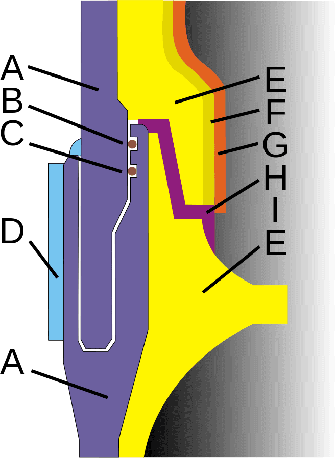
- Consider the cross-sectional view in Fig. 02. The booster ignition caused the heat-resistant putty to displace and increase air pressure between the putty and O-ring. This caused the gap between the ring (A) and insulation (E) to increase.
- Due to exposure to hot gases, the O-rings underwent erosion.
- On the shuttle Flight 51-C on 24th January 1985, blow-by was observed. This meant that the hot gases had penetrated both O-rings completely. This launch was done at the lowest ambient temperature.
Further tests in March 1985 demonstrated that the O-ring resiliency had issues when used below 10°C. On the 31st July 1985, a memo circulated that discussed a definite fear of losing a flight due to these conditions.
On the days before the launch, engineers continuously raised the issue about launching in cold conditions. Unfortunately, the issue eventually died down despite many engineers feeling that their concerns were not addressed. Further on, as commonly believed, there was no pressure to launch despite the delays. At this juncture, it is interesting to understand the flow of decision making. The two most notable decision makers included:
- Engineers: Morton-Thiokol Inc. (MTI, company manufacturing O-ring), Roger Boisjoly (O-ring specialist), Arnold Thompson (Engineer), Allen McDonald (Project supervisor of solid fuel rocket), Jerry Mason (Senior VP & GM), Joe Kilminster (VP of Space Booster), Robert Lund (VP, Engineering)
- NASA: Larry Mulloy (Manager of solid rocket booster), George Hardy (NASA Deputy Director)
Download this case study to learn how a ducting system design was optimized with CFD simulation 100% via web browser.

The Eve of the Launch
On the eve of the initial launch date, the MTI engineers and management recommended to delay the launch because the temperature was too low (less than 10°C). It later came out that Kilminster in particular was opposed to the launch, while Mulloy wanted to press on. As per NASA’s regulations, it was the responsibility of the contractor to demonstrate launch readiness of the components. Any inconclusive data automatically resulted in a no-go. However, Larry Mulloy put the burden on MTI to prove that the system was not ready.
Amid all the politics, Robert Lund—who was initially reluctant—agreed to the launch along with Jerry Mason. While Allen McDonald argued against the launch, Joe Kilminster declared to NASA that the data was inconclusive & hence a launch is not recommended. At this point, NASA managers Larry Mulloy & George Hardy, inform MTI that they can only make recommendations and they wanted to go ahead with the launch. They informed the higher-ups about going ahead, ignored the concerns raised, and unfortunately made history. We all know what happened next.
The Space Shuttle Challenger Launch
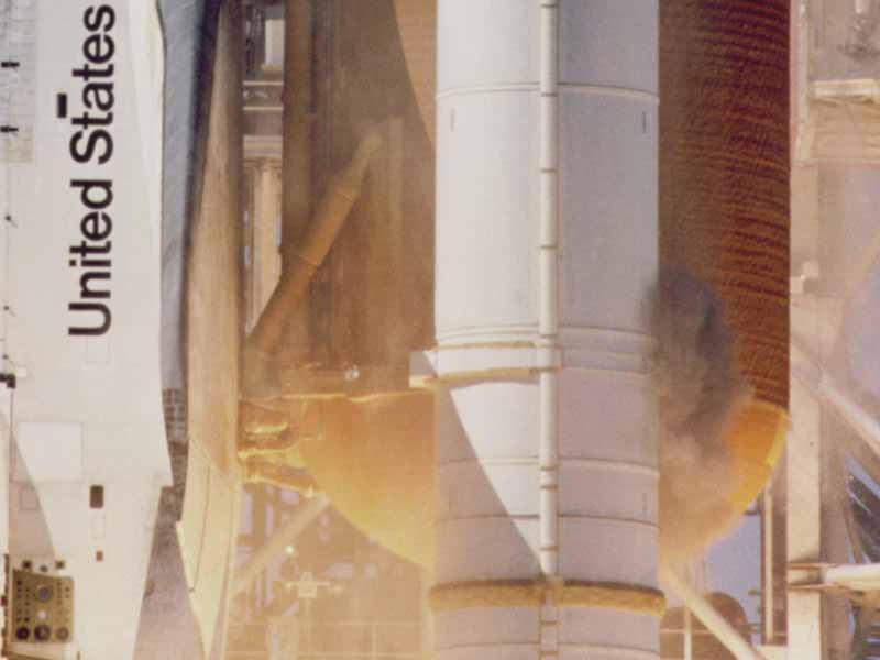
Going ahead, the shuttle was launched. The temperature, as predicted, was low enough for the rings to be extremely stiff and not provide sufficient sealing. As shown in Fig. 03, plumes of smoke were immediately visible.
Due to the pressure of the launch, the cylindrical containers/casing bent away from each other creating an opening. The O-rings were expected to shift to seal the gap. However, due to low temperatures below the glass transition temperature, the O-rings behaved in a glassy and brittle manner. Above these temperatures, they demonstrated extreme flexibility and elasticity. Thus, it took much longer for these O-rings to shift out of place and create a seal. Both O-rings were vaporized across a 70° arc allowing gases to leak through a growing hole. That day, the shuttle experienced more than normal wind shears, leading to rapidly increasing hole.
At 73 seconds past launch, the disintegrating external tank caused the shuttle to veer from its altitude. This increased the aerodynamic forces to more than 20g (beyond its design limit of 5g) resulting in the breakup of the shuttle. The SRB’s continues to propel in an uncontrolled fashion. The intact cabin then flew into the Atlantic ocean with the crew likely conscious almost until impact.
Conclusion
The Challenger disaster was broadcasted worldwide and played time and again. To this day, people feel that they personally witnessed the disaster, and were somehow connected. A major factor was failure to effectively test polymeric material behavior across a range of temperatures. This, along with several other contributing engineering faults, eventually led to the tragedy. The Challenger disaster is an infamous example of how even the simplest engineering concepts must be respected, tried, and tested or misfortune can strike- and sometimes be fatal.