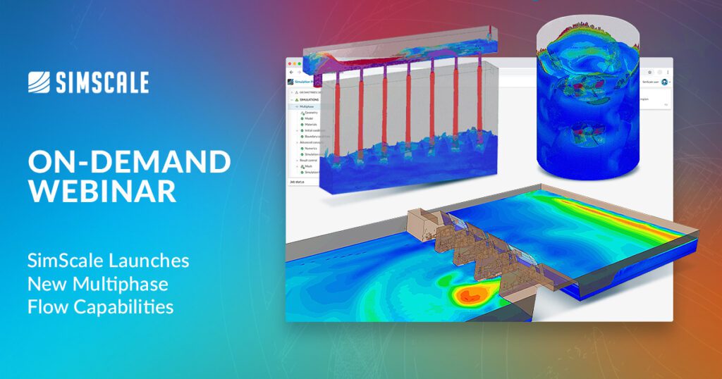
Multiphase flows are ubiquitous in engineering and natural processes and are often resource intensive to simulate. SimScale has launched a new set of features that enable fast and accurate multiphase flow simulation and modeling in the cloud.
Engineers can leverage SimScale’s proprietary multiphase solver to realize simulation results within a few hours, gain reliable insight into the underlying physics, and make fast design decisions — all through a web browser. The multiphase features released so far lend themselves to the following focus application areas:
- Hydraulics engineering (dams, spillways, reservoirs, tanks)
- Industrial equipment (mixers, separators, cooling channels)
- Rotating machinery (pumps and water turbines)
- Valves and flow control devices
In this article, we show some multiphase simulation projects from different industries to showcase the newly released multiphase capabilities, in particular:
- How to run a free surface simulation
- How to simulate an industrial multiphase problem with rotating zones
- How to post-process multiphase simulation results easily within SimScale
- How to leverage cloud-native simulation for accelerated design space exploration
Multiphase Flow Simulation in SimScale
SimScale offers several advantages to engineers wishing to perform multiphase simulations.
Industry-validated CFD Method
- Volume-of-Fluid algorithm with proprietary, higher order interface reconstruction scheme.
- Comprehensive physics with real fluid properties, suitable for various flow regimes
- Currently, only two-phase simulations are possible, with an extension to n-phase analysis to be released in 2023
- Automatic CFL adjustment at the interface; fast convergence with no babysitting
Robust & Automatic Meshing
- Minimal CAD clean-up required using proprietary CAD handling and meshing
- High-quality Cartesian hex mesh in an automatic one-step process
- The binary tree algorithm judiciously places mesh cells and refines user-defined areas economically.
- Easy handling of micron-size gaps and clearances
Intuitive Simulation Setup & Low Runtimes
- Transient-free surface and multiphase simulation results within a few hours. This is a result of a proprietary numerical algorithm with inherently fast convergence and runtime.
- User-friendly UI with physics-based pre-populated inputs and simulation templates
- Default material library with customization options
- Design of Experiments
- Unlimited parallel simulations for CAD and operating condition parameterization
- CAD associativity for easy geometry variation
Let’s take a look at some multiphase simulation examples. Users can find many more simulation projects on the SimScale projects library, and the following examples can be viewed in more detail on the Multiphase Launch on-demand webinar.
Multiphase Flow Simulation in Practice
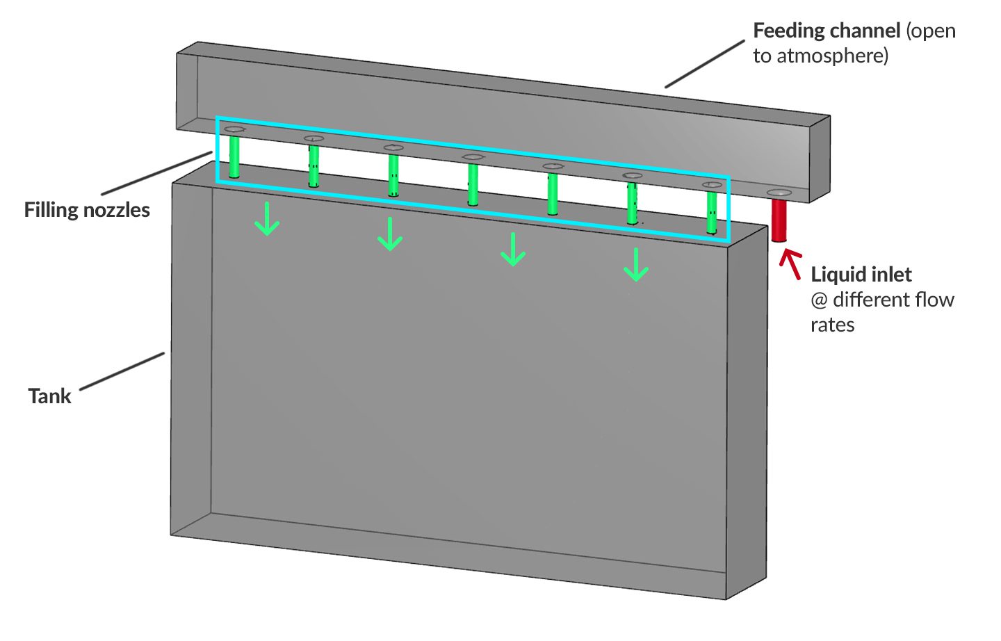
Optimization of multi-intake tank filling process
A multi-intake tank is simulated using the multiphase features in SimScale. The main design goals are to calculate and optimize filling time, improve filling efficiency, and avoid feeding any channel overflow. The tank has one inlet (red) and seven feeding nozzles in sequence (green) and as shown in the image below.
An initial design is simulated with water as the filling liquid at a flow rate of 0.1 m3/s. The simulation is transient, and an 80-second simulation time is run, taking 2.5 hours to complete and consuming 10 CPUh (core hours). The initial design has reduced filling efficiency (image below). The design suffers from water spilling out from the top channel, which is open to the atmosphere, and escaping air is blocking some of the feeding nozzles.
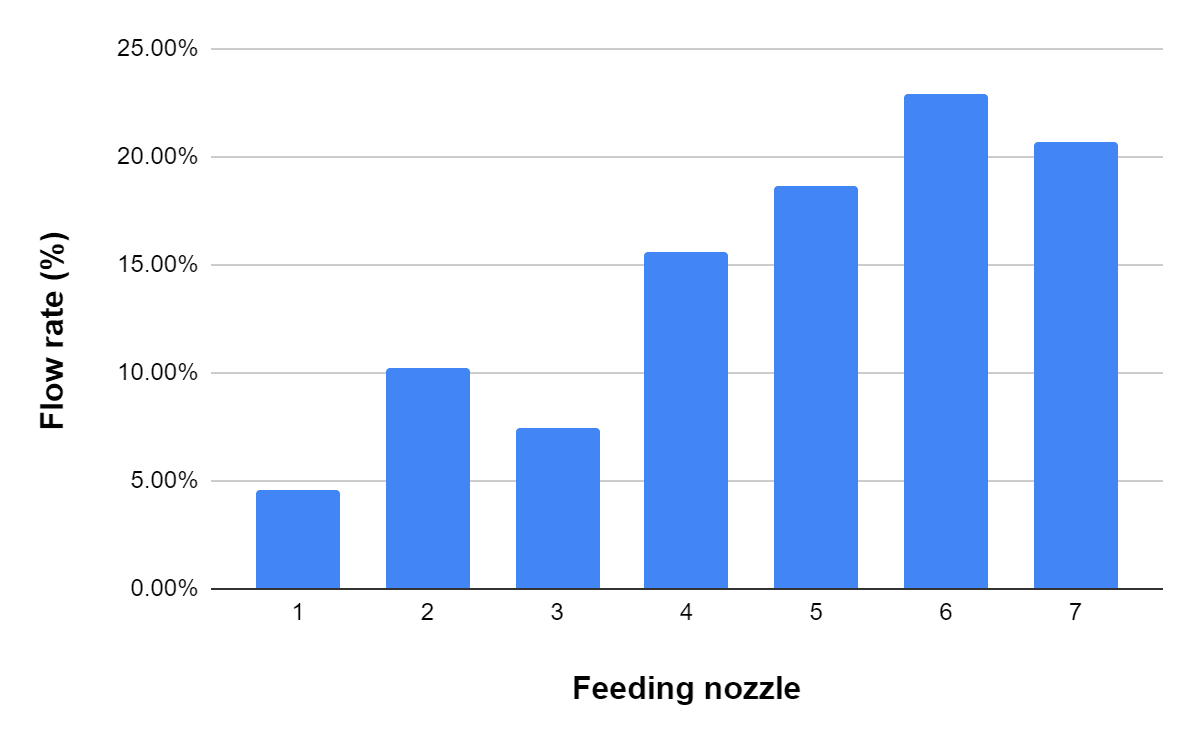
A revised case with a pressure relief opening (circled in red) added offers some improvement, but there is still significant uneven flow through each nozzle and overspill from the top channel. The chart in Figure 5 shows the uneven flow rates through the seven nozzles as a percentage of the total, with a variation of 20% between the highest and lowest.
A further iteration is made by adding a deflector at the inlet side. The addition of a deflector allows for increasing the supply flow rate to 0.18 m3/s without spilling over the top channel and gives uniform nozzle performance. The higher flow rate ensures all nozzles are receiving a similar flow rate at the same time and the tank is filled in less than 80 seconds.
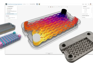
Industrial Mixing Tank
An industrial mixing tank is simulated to:
- optimize its mixing efficiency
- calculate the required impeller power
- evaluate mixing behavior at different rotational speeds and design configurations.
There are many attributes of the mixing tank that can be altered to achieve an optimum design. Variables such as the tank shape, number of blades on the impeller, rotational speed, use of counter-rotating impellers, etc., can all be analyzed in SimScale, leveraging parametric simulation on the cloud. In this case, we have two options, the baseline design and one with baffles. Both are rotating in a clockwise direction at 200 rpm, and a transient simulation for 5 seconds simulation time is run.
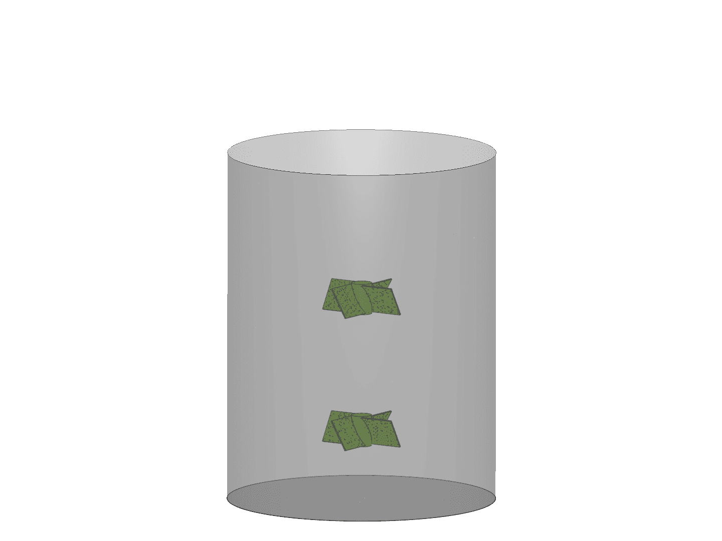
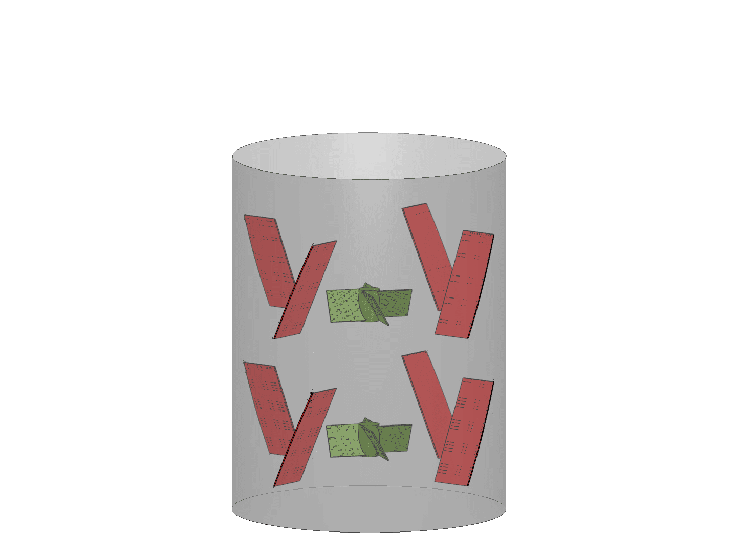
Figure 7: Final design variation with a deflector added at the inlet.
The images below show a comparison of the two designs and how the mixing in the tank occurs. Although the baseline design naturally uses less power, the design with baffles allows better top-down mixing and has lesser air entrainment in the central vortex. Overall, mixing is better in the design with baffles. Tank aeration from a sparger can also be studied in the same analysis.
On-Demand Webinar
Watch our latest webinar on SimScale’s new multiphase flow capabilities by clicking on the image below.