As the world races toward Net Zero, engineers face an urgent challenge: design electric motors that are more efficient, more powerful, and more durable than ever before.
From electric vehicles (EVs) and robotics to industrial machinery and HVAC systems, electric motors power critical infrastructure—and consume over 40% of global electricity.
The solution? Advanced electric motor design software powered by cloud-native simulation.
Modern motor design demands multiphysics optimization across electromagnetics, thermal management, and structural analysis.
Physical prototyping is too slow and expensive!
Simulation enables engineers to test, iterate, and optimize designs in hours instead of weeks, slashing development costs while maximizing efficiency and power density.
This guide covers the complete electric motor design workflow; from fundamental principles and motor types to the six-stage design process and multiphysics simulation techniques that deliver optimal performance.
Already familiar with electric motor fundamentals?
Skip to the Electric Motor Design Process →
Electric Motor Fundamentals: How They Work and Their Types
An electric motor converts electrical energy into mechanical motion through electromagnetism. When current flows through a wire coil in a magnetic field, it creates rotational force.
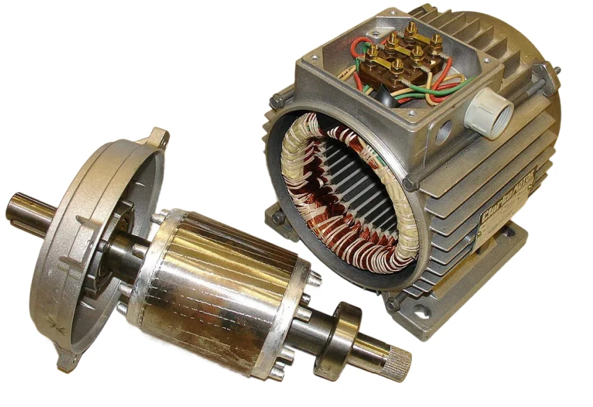
The motor consists of two main parts: the stator (stationary, houses windings that generate magnetic fields) and the rotor (rotating, produces mechanical output). Additional components include windings (copper or aluminum coils), and for DC motors, commutators and brushes that control current direction.
Types of Electric Motors
Electric motors are classified primarily by power source: DC (direct current) or AC (alternating current).
| Motor Type | Power Source | Key Application Areas |
|---|---|---|
| Brushed/Brushless DC (BLDC) | Direct Current (DC) | Robotics, EVs, drones, small appliances |
| Induction (Asynchronous) | Alternating Current (AC) | Industrial machinery, pumps, HVAC blowers, general purpose drives |
| Synchronous (PMSM) | Alternating Current (AC) | High-performance EVs, precision positioning equipment |
Comparative Motor Selection Guide
Choosing the right motor type depends on your specific application requirements:
| Motor Type | Efficiency | Power Density | Cost | Maintenance | Lifespan | Best For |
|---|---|---|---|---|---|---|
| Brushed DC | 75-80% | Moderate | Low | High | 1,000-3,000 hrs | Cost-sensitive, simple control, low-duty cycle |
| Brushless DC (BLDC) | 85-90% | High | Moderate-High | Very Low | 10,000+ hrs | EVs, drones, robotics, continuous operation |
| AC Induction | 85-96% | Moderate | Low-Moderate | Low | 20,000+ hrs | Industrial machinery, reliability-critical |
| Synchronous (PMSM) | 90-98% | Very High | High | Low | 15,000+ hrs | High-performance EVs, aerospace, maximum efficiency |
| Switched Reluctance (SRM) | 85-93% | Moderate-High | Low | Very Low | 20,000+ hrs | Harsh environments, no rare-earth magnets |
Key Selection Factors:
- Efficiency priority: Synchronous PMSM > BLDC > AC Induction
- Cost sensitivity: Brushed DC or SRM > AC Induction > BLDC > PMSM
- Power-to-weight ratio (aerospace, EVs): PMSM > BLDC > SRM
- Harsh environments: SRM or AC Induction
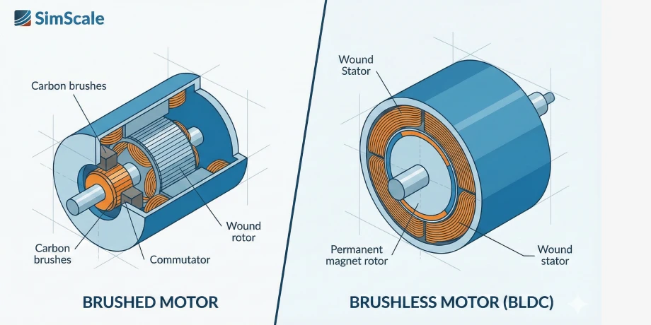
Brushed vs Brushless: Performance Comparison
Performance: Brushless motors achieve 85-90% efficiency vs 75-80% for brushed, deliver 30-50% more power for the same size, and operate from 0 to 50,000+ RPM (vs ~10,000 RPM for brushed).
Operational: Brushed motors require brush replacement every 1,000-3,000 hours; brushless are maintenance-free with 10,000+ hour lifespans. Brushless motors run quieter but require electronic controllers (ESCs), adding cost and complexity.
Cost: Brushed motors cost 30-60% less initially, but brushless offer lower total cost of ownership due to longer life and higher efficiency.
When to Choose: Brushed for low-cost, simple applications; brushless when efficiency, continuous operation, and reliability are prioritized.
Explore detailed motor testing methodologies in our guide: How to Test an Electric Motor: Tools and Methods.
Electric Motor Design Process
The electric motor design process involves six critical stages:
1. Define Design Requirements
Establish clear specifications including performance targets (power, torque, speed, efficiency), operating conditions (temperature, duty cycle), size/weight constraints, and cost parameters. Energy consumed over a motor’s 20-year life typically represents 70-95% of total cost, making efficiency optimization critical.
2. Select Motor Type and Topology
Choose between AC, DC, synchronous, or induction motors based on application requirements. Decide on permanent magnet vs wound rotor configurations and determine number of poles and phases—decisions that directly impact torque, speed range, and control complexity.
3. Initial Design Calculations
Perform preliminary electromagnetic calculations to size the magnetic circuit and determine winding configurations. Calculate expected heat generation and select appropriate materials:
Key Material Choices:
- Magnetic cores: Silicon steel (M19 standard, M15 premium), amorphous metals for ultra-low losses
- Permanent magnets: NdFeB N35-N52 grades (higher = stronger but lower temp tolerance), SmCo for high-temperature applications (up to 350°C)
- Conductors: Copper (standard, 100% conductivity) or aluminum (40% lower cost, 61% conductivity)
- Insulation: Class 155-240 by temperature rating (155°C industrial to 240°C aerospace)
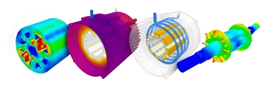
4. Detailed Design with Simulation
Simulation validates and refines designs through:
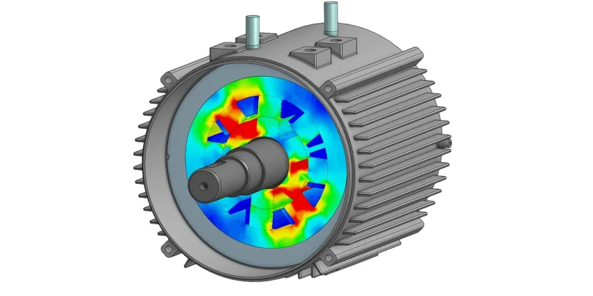
- Electromagnetic simulation: Visualize magnetic flux, calculate torque, identify saturation or losses
- Thermal simulation: Predict temperature distribution, design cooling systems
- Structural FEA: Ensure components withstand operational stresses and vibrations
5. Design Optimization
Conduct parametric studies varying geometry, materials, and winding patterns. Run multi-objective optimization balancing efficiency, power density, cost, and manufacturability. SimScale’s cloud platform enables unlimited parallel simulations, exploring entire design spaces in hours instead of weeks.
6. Prototype and Testing
Virtual prototyping through comprehensive multiphysics simulation predicts real-world performance across operating conditions. Physical prototypes validate predictions before full production.

“Developing a product like this from scratch requires a lot of simulation work across multiple physics to explore all of the possibilities in the design space. Getting speed, accuracy, usability, and cost efficiency in one package is hard to find anywhere else.”
Maximilian Güttinger
CEO & Co-founder, Emil Motors
Environmental Design Considerations
Extreme environments demand specialized design approaches:
High-Temperature (Aerospace, Industrial): Use SmCo magnets (vs NdFeB), Class 200+ insulation, enhanced cooling, ceramic bearings for operation above 150°C.
High-Vibration (Automotive, Construction): Strengthen rotor balancing, use press-fit magnets, specify preloaded bearings, conduct modal analysis to avoid resonant frequencies.
Corrosive Environments (Marine, Chemical): Implement IP67/IP68 sealing, epoxy coatings on windings, stainless steel housings, sealed bearings.
Vacuum/Space: Use dry lubricants (MoS₂, PTFE), low-outgassing materials, conduction-only cooling, ceramic or magnetic bearings.
Electric Motor Design with SimScale
SimScale’s cloud-native platform offers comprehensive multiphysics simulation without hardware limitations, running directly in web browsers.
Electromagnetic Design and Simulation
Analyze magnetic fields, calculate torque and eddy current losses, and determine winding inductance and resistance. SimScale’s magnetostatics and time-harmonic magnetics capabilities enable engineers to optimize motor designs before physical prototyping.
SimScale provides step-by-step guides such as the Time-Harmonic Electromagnetics Simulation on a 3-Phase Transformer and the Electromagnetics Simulation on a Magnetic Lifting Machine.
Thermal Management
Conjugate Heat Transfer (CHT) analysis predicts temperature distribution across the motor. Engineers can design effective air or liquid cooling systems, optimize flow paths, and identify hotspots caused by copper losses and core losses before building prototypes.
Structural Analysis
Finite Element Analysis (FEA) using SimScale’s structural mechanics capabilities assesses mechanical stress on shaft-rotor assemblies, performs modal analysis to avoid destructive resonance, and predicts fatigue life. This ensures structural integrity under high speeds, rapid acceleration, and thermal stresses.
Learn advanced techniques in our Advanced Structural Analysis for Electric Motor Shaft and Rotor Design Webinar.
Structural Validation: Rotor Dynamics at 16,000 RPM
“FEA simulations revealed that centrifugal forces caused the rotor discs to ‘dish’ away from the central stator at high speeds. This was a very helpful discovery, since it effectively works as a self-governing mechanism to prevent contact between the rotors and stator. It’s a critical consideration with an air gap of only 0.6mm.”
Maximilian Güttinger
CEO & Co-founder, Emil Motors
Cloud-Based Optimization
SimScale’s cloud infrastructure provides:
- Scalability: Run unlimited parallel parametric studies exploring entire design spaces
- Accessibility: Complex multiphysics models run in any web browser, no specialized hardware required
- Collaboration: Teams share projects globally via URLs, enabling real-time feedback
This approach reduces simulation time from weeks to hours while eliminating expensive workstation requirements.
Ease of Use Advantage
SimScale is easily the best implementation of OpenFOAM that we have ever used, and it has significantly accelerated the development of our next vehicle’s aerodynamic body. The customer support team at SimScale is unrivaled in their friendliness and efficiency.
Joel Khristy
Aerodynamics Engineer, Illini Solar Car
The team delivered an optimized design in just 2 weeks and identified 2 major design changes, enabling them to compete in the American Solar Challenge and Bridgestone World Solar Challenge.
Electric Motor Design: Cost and Timeline Considerations
Understanding investment requirements helps engineers plan effectively.
Budget Ranges by Motor Category
| Motor Category | Design & Engineering | Prototype & Testing | Total Development |
|---|---|---|---|
| Simple BLDC (sub-kW) | $5,000 – $15,000 | $3,000 – $8,000 | $8,000 – $23,000 |
| Custom Industrial (5-50 kW) | $15,000 – $50,000 | $13,000 – $40,000 | $28,000 – $90,000 |
| High-Performance (automotive, >90% efficiency) | $50,000 – $150,000 | $35,000 – $100,000 | $85,000 – $250,000 |
| Specialized/Certified (aerospace, military) | $100,000 – $300,000 | $70,000 – $180,000 | $170,000 – $480,000 |
Development Timelines
Standard Development: 16-31 weeks (4-7.5 months) including requirements, design, prototyping, testing, and iterations.
Accelerated with Simulation: 8-16 weeks (2-4 months). Parallel simulation studies reduce iteration cycles by 40-60%, and virtual prototyping eliminates 1-2 physical prototype cycles.
Certified Motors: Add 6-12 months for UL, CE, or MIL-SPEC certification and environmental qualification.
How Simulation Reduces Costs
Traditional Approach: 3-5 physical prototype iterations at $5,000-$30,000 each = $15,000-$150,000 total.
Simulation-Driven: Virtual prototypes reduce physical builds to 1-2 validation units only.
Savings: $10,000-$100,000 per project plus 8-16 weeks accelerated time-to-market.
SimScale Advantage: No $15,000-$40,000 workstation investment, unlimited parallel optimization, and global team collaboration enable faster innovation cycles.
Start Simulating Now
Electric Motor-Driven Systems account for over 40% of global electricity use. Marginal efficiency improvements are critical for sustainability targets and meeting global MEPS regulations.
The ultimate challenge for motor OEMs is consistently delivering high-performance, high-efficiency designs while minimizing Total Cost of Ownership. Cloud-native simulation in SimScale provides the speed and multiphysics insight to replace slow, costly physical prototyping.
SimScale offers cutting-edge solvers integrated into a cloud-native interface, enabling multiple parallel simulations directly in your web browser—no expensive hardware required.