Dynamic response analysis and dynamic shock analysis are prominent Finite Element Analysis (FEA) applications in various engineering disciplines, including automotive, aerospace, and civil engineering.
Their purpose? To explain how structural systems behave when they are subjected to dynamic loadings.
Imagine you’re standing on the edge of a freeway, watching cars whizz by, or perhaps looking at a towering skyscraper standing firm against a turbulent wind. The forces and movements you observe are dynamic, constantly changing, imposing loads that challenge these structures.
This article delves deep into understanding the dynamic response, dynamic shock analysis, and their nuances. We will explore the implementation of these analyses in SimScale and how a cloud-native platform enables such FEA simulations. This article also sheds light on the intricate processes of these simulations and the subsequent interpretation of results for optimal system design.
What Is Dynamic Response Analysis?
Dynamic response analysis involves analyzing the behavior of structures under dynamic loading conditions (loads that can change in magnitude, direction, or frequency over time).
Picture a structure under dynamic loads: The load magnitude fluctuates, the direction alternates, and even the frequency evolves with time. Static studies tend to perceive these loads as constant, overlooking essential factors like damping and inertial forces.
However, reality often defies these assumptions. Loads are dynamic, varying with time and frequency.
Dynamic response analysis is designed to address this deficiency by providing a methodology to handle non-constant load conditions. It is typically employed when the frequency of a load exceeds one-third of the basic frequency.
To get a sense of the distinction between static analysis and dynamic analysis, consider the equations used in finite element models:
$$ [K] \vec{u} = \vec{F} \tag{1}$$
$$ [M] \ddot{\vec{u}} + [C] \dot{\vec{u}} + [K] \vec{u} = \vec{F} \tag{2}$$
Where \(\vec{F}\) the load vector, \([K]\) is the global stiffness matrix, \([M]\) is the global mass matrix, \([C]\) is the global damping matrix, \(\vec{u}\) is the displacement vector, \(\dot{\vec{u}}\) is the velocity vector, and \(\ddot{\vec{u}}\) is the acceleration vector.
\([M] \ddot{\vec{u}}\) is the inertial force (i.e., mass times acceleration) and \([C] \dot{\vec{u}}\) represents the damping force (i.e., damping coefficient times velocity). These terms represent the dynamic forces that distinguish dynamic simulations from static simulations.
The computation of this analysis is typically conducted via simulation software, which determines the simulation’s characteristic response by integrating each mode’s contribution to the load.
The value of using dynamic response analysis depends on various aspects of loading:
- How often it changes (load frequency)
- How big it is (load magnitude)
- Which way it’s going (load direction)
- How long it lasts (load duration)
- Where it’s applied (load location)
Dynamic response analysis can be further subdivided into several types of analysis, namely modal analysis, harmonic response analysis, and transient dynamic analysis.
Modal Analysis
Modal analysis is an analysis type that identifies the inherent dynamic properties of a system in order to create a mathematical model, called the modal model, that describes its dynamic behavior using modal data. It helps define the system’s natural characteristics, such as its natural frequency, damping, and mode shapes (mode shapes represent the characteristic displacement pattern of the system).
By studying the frequency and position of a structure, modal analysis enables us to specify when the system would experience resonance, which is the point at which the applied excitation is equal to the system’s natural frequency. This helps make informed design decisions so that phenomena like resonance are avoided.
Harmonic Analysis
Harmonic analysis is a type of dynamic response analysis that simulates the steady-state behavior of solid structures subjected to periodic loads, providing frequency-dependent results. In other words, it studies the response of linear structures under a load varying sinusoidally with time.
Harmonic analysis is particularly useful for evaluating the effects of vibrating forces or linear displacements over a range of frequencies.
Transient Dynamic Analysis
Transient dynamic analysis is a method used to assess the behavior of deformable bodies under conditions where inertial effects play a significant role. It provides time-dependent results, making it particularly useful for evaluating the effects of rapidly applied loads.
| Conditions | Recommended Analysis |
| Inertial and damping effects can be ignored. | Linear or Nonlinear Static Analysis |
| Purely sinusoidal loading and linear response are considered. | Harmonic Response Analysis |
| Bodies can be assumed to be rigid, and kinematics of the system are of interest. | Bodies can be assumed to be rigid, and the kinematics of the system are of interest. |
| Any other case | Transient Structural Analysis |
What Is Dynamic Shock Analysis?
Dynamic shock analysis specifically focuses on the response of a structure or system to sudden, high-intensity loads or impulses. It aims to assess the behavior and integrity of the structure under extreme loading conditions, such as impact, collision, or explosive forces.
Imagine an extreme scenario – an automotive crash structure colliding, an aircraft experiencing a hard landing, or an electronic device enduring a drop impact.
This is where dynamic shock analysis takes the stage, specializing in understanding how your design would respond to sudden, high-intensity loads.
While dynamic response analysis is a generalist, shock analysis is a specialist, addressing the extraordinary events where high-intensity, rapid-loading events are involved. By doing so, it helps optimize designs for maximum energy absorption and minimum deformation, predicts potential failures for safety enhancement, and even aids in meeting regulatory requirements.
What Is Dynamic Shock Analysis Used for?
Design Optimization
It helps optimize the design of automotive crash structures, ensuring they can absorb maximum impact energy while minimizing deformation and reducing the risk of occupant injury.
Safety and Failure Prediction
It enables the assessment of structures subjected to sudden loads, such as aircraft components during a hard landing, to predict potential failures and improve safety measures accordingly.
Regulatory Compliance
Dynamic shock analysis assists in meeting regulatory requirements, such as testing electronic devices to ensure they can withstand drop impacts within specified limits.
Research and Development
It aids in developing resilient and durable materials for applications like protective gear, where the analysis evaluates their ability to absorb and dissipate impact energy effectively.
FEA for Dynamic Response and Shock Analysis
Imagine being able to simulate the dynamic and shock conditions your design would endure and predict its response – without physical trials. That’s the power of finite element analysis (FEA).
By creating computerized models of structures and applying suitable loads and boundary conditions, you can foresee how these structures would react to dynamic loads and shocks.
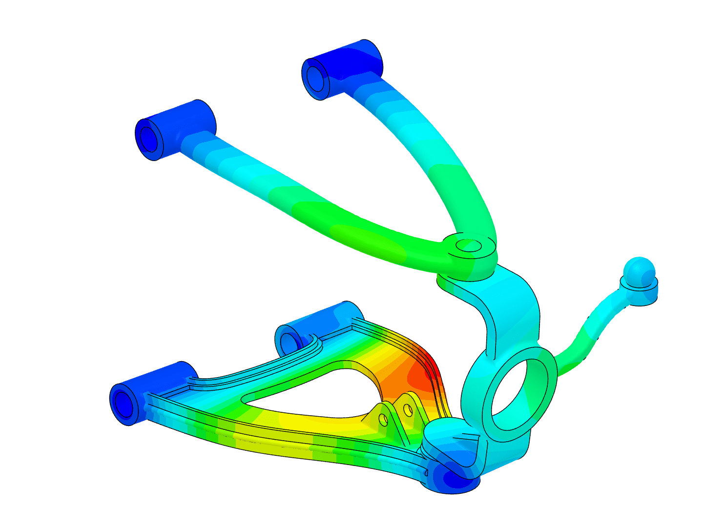
The methodology of FEA involves breaking down the structure’s model into thousands of small, interconnected ‘finite elements.’
These elements closely represent the intricate features of the structure, thus enabling accurate calculations of stress, strain, and displacement under dynamic and shock loadings.
To learn more, check out this step-by-step guide to dynamic analysis.
Now, let’s go one step further and introduce SimScale into the equation. This is where your journey toward efficient and accurate solutions begins. SimScale’s Structural Mechanics software is a powerful tool that allows engineers to virtually test and predict the behavior of their designs under dynamic and shock conditions.
Maximize Efficiency with SimScale Simulation
SimScale’s cloud-native platform enables engineers and designers to simulate early in the design process without the hassle of software installation and expensive hardware. It empowers design teams and simulation experts alike to test their designs under various conditions by running multiple simulations simultaneously using the power of the cloud. This minimizes the testing time significantly and enables quicker design optimizations, thus enabling faster innovation. Experience the power of collaboration, innovation, and optimization with SimScale’s cloud simulation, accessible anytime, anywhere. Simply sign up, import your 3D design, and start simulating immediately in your web browser.
Nevertheless, the benefits of SimScale don’t stop at accessibility. It also brings your projects into the collaborative sphere, allowing you to share them with your colleagues and teams. This facilitates rapid design improvement and significantly shortens your workflow.
Take, for instance, TechSAT, a prominent company in the aerospace industry. They use SimScale’s simulation capabilities to optimize and validate the performance of their products. SimScale has significantly reduced TechSAT’s time to develop new products. Here is what other customers have said about SimScale.
If you’re an engineer or a product developer eager to make your design process more efficient and speed up your innovation process, it’s time to take advantage of cloud computing and take the next step towards efficient and accurate engineering solutions with SimScale’s cloud-native platform. Sign up below or request a SimScale demo today.