Understanding how a valve operates across a range of operating conditions is critical in characterizing its overall performance. Industry standards, such as Cv, have been developed to normalize how valve performance is evaluated. Cv is a relative value which measures flow rate for a given pressure delta across the valve. The bigger the Cv, the more flow a valve can pass for a defined pressure drop. Cv allows a design engineer to quickly compare different models or brands of valves, as well as find the best fit for their application.
What is a Globe Valve?
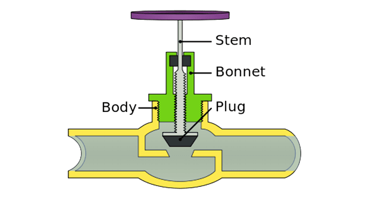
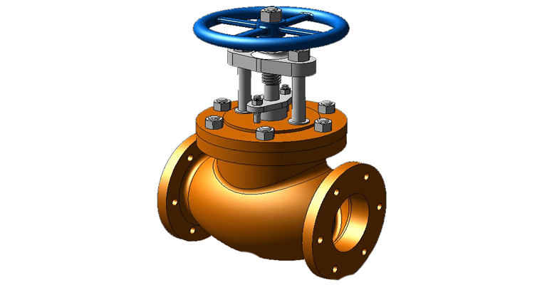
A globe valve regulates flow through vertical linear motion of a globe-shaped plug. Each globe valve consists of a main body, stem, plug (i.e., “globe”), and bonnet. It is primarily used for regulating fluids which are corrosive or have high viscosity. Due to its inherent shape, most of the fluid will drain off on the discharge side if the valve is completely closed, which minimizes the chances of corrosion or clogging.
Simulating Pressure Drop Case Study: Predicting Pressure Drop through a Globe Valve
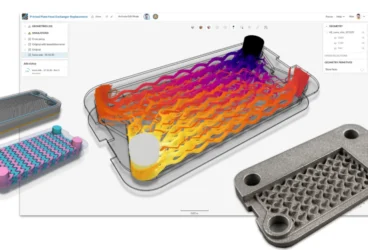
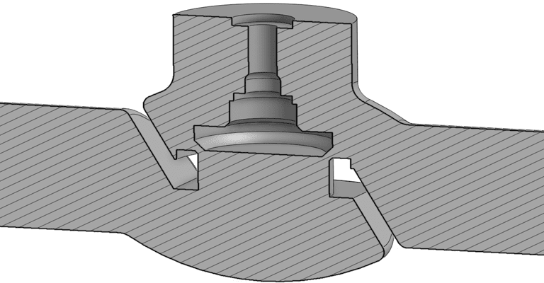
The geometry used for the case simulation was taken from GrabCAD as a standard globe valve, with flow going from left to right within the model as pictured below. The CFD simulation answers two questions: What is the resulting flow rate for a given pressure drop? And how does this change with respect to plug position? Furthermore, fluid forces on the plug can be monitored to evaluate structural performance.
With the given CAD model, the fluid domain has not yet been defined. For the next step, it is necessary to extract the flow volume based on the current geometry. This can be done automatically in the SimScale platform.
To learn more about the CFD simulation capabilities of the SimScale platform, download this features overview.
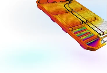
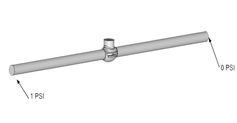
The resulting body is the negative of the valve geometry, as shown below. In preparation for simulation, both an inlet and outlet pipe extension were added on to allow enough entrance length for fully developed flow.
Globe Valve Optimization What is The End Goal of The Simulation?
The purpose of the simulation is to calculate the flow coefficient. As an industry standard, it describes the flow rate across an orifice, valve or another assembly for a given pressure drop. This equation uses gallons per minute for units of flow rate, and pounds per square inch for pressure. The specific gravity value is usually set to 1, which is the specific gravity of water. The standard simulation setup consists of defining a 1 psi pressure drop across the valve and then running a CFD simulation to evaluate the flow rate.

Getting Started Valve Simulation Setup
A 1 PSI pressure boundary condition was defined at the inlet, and a 0 pressure boundary condition was defined at the outlet. A simulation was run to calculate the flow rate at 6 different plug positions: 1, 2, 4, 6, 8, and 10 mm. All six simulations were run simultaneously on 32-core machines, which rapidly increases the turnaround time when compared to traditional desktop CFD software.
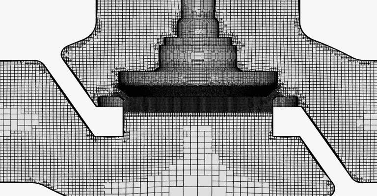
A hex-dominant automatic mesh was used with a general fineness setting set to moderate. To increase the accuracy of the results, feature refinement, surface refinement, region refinement, and wall layers were also added to further enhance the mesh.
CFD Simulation CFD: Incompressible Analysis of a Globe Valve
The geometry was then uploaded to the SimScale platform and incompressible flow simulation—which is used when fluid velocity is much less than the Mach number—was selected. The SST k-omega turbulence model was used, and the analysis was run as steady state. Water was assigned to the single CAD body. The simulation was run for 1000s (or iterations) using 32 computing cores.
Globe Valve Pressure Drop Analysis Results
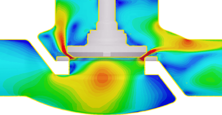
As expected, the highest velocity was between the plug wall and seat.
One unintuitive finding is the velocity jet on the left side of the plug. Instead of jetting out parallel to the plug/housing wall, it instead shoots straight up in the vertical direction. This is in contrast to the right side of the plug, which has a more predictable velocity jet. This can be visualized by a cut-plane showing velocity magnitude through the cross-section.
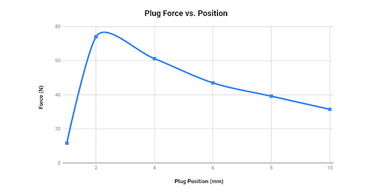
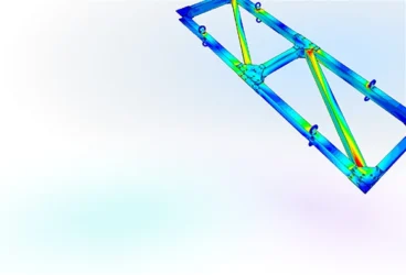
The above graph shows the force on the plug at different plug position openings. The position vs. force curve for a globe valve in very unpredictable, and it is hard to judge where the maximum force may occur. As shown above, the globe valve plug saw its highest forces while 2 mm open.
Watch the recording of our recent webinar on the same topic by filling out a short form here and check out our published slide deck for more information.