websights

Fill out the form to download

Required field
Required field
Not a valid email address
Required field
Required field

Griffon Hoverwork: Hovercraft Design for
Challenging Marine Environments

Challenge

  • Design hovercraft for challenging marine environments. 
  • Evaluate rudder and propeller performance using CFD.
  • Calculate limits of rudder loading for various operating conditions.

Results

  • Simulated the propeller and rudder CAD model using CFD in SimScale.
  • Finalized rudder loading using CFD and FEA for critical use cases. 
  • Significantly reduced physical prototyping costs by simulating multiple CAD variants in parallel in the cloud
a close up of the propellers and rudders
a close-up of the propellers and rudders. The image shows loading on the rudders.

Marine Craft for Challenging Environments

Griffon Hoverwork is a world leader in hovercraft design and manufacturing of hovercraft and has been involved in hovercraft development since they were first conceived, over 50 years ago. The company develops pioneering new products and solutions and offers expert advice, training, and consultancy. Over 180 Griffon Hoverwork craft operate in 41 countries, in extremely inaccessible and challenging environmental and geographical conditions. Griffon customers all have one thing in common — a need to access areas where conventional marine craft cannot operate. A core capability in designing and manufacturing hovercraft which are adapted to challenging environments is the use of simulation to virtually test and optimize craft performance.

a Griffon Hoverwork Hovercraft in operation
Figure 1: A Griffon Hoverwork Hovercraft in operation

Simulation at Griffon Hovercraft

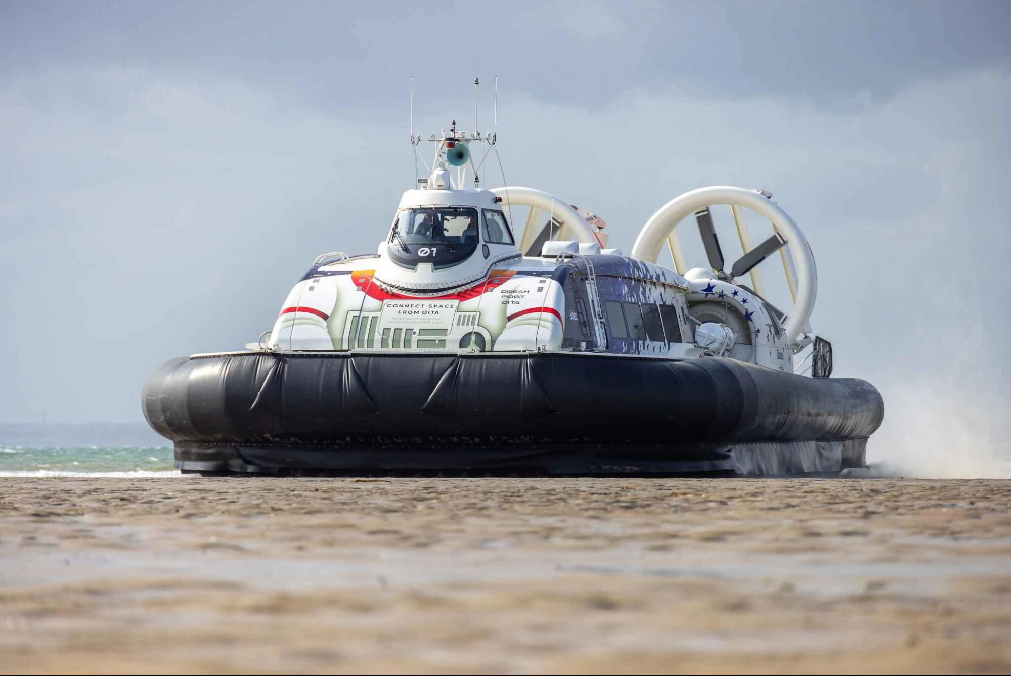
Hovercraft developed at Griffon can be customized to meet different mission and environmental conditions. They are used for various purposes, including:

  • Commercial: passenger transportation, survey and research, logistics and cargo delivery, search and rescue, and mobile medical clinics.
  • National Security: border patrol and surveillance, policing and customs duties, marine interdiction, and infrastructure security.

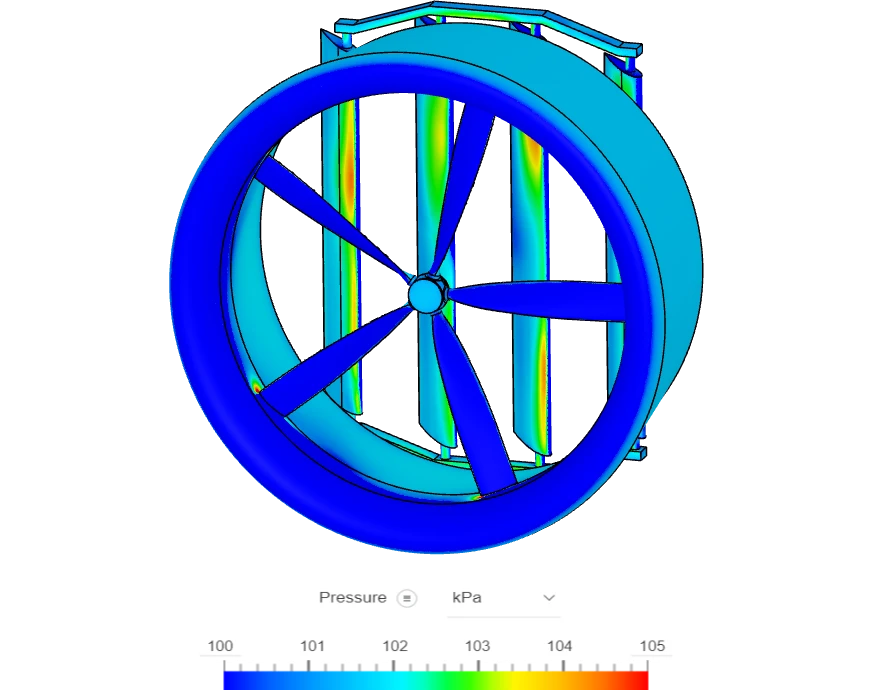
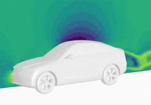
At Griffon Hoverwork, CFD simulations are an essential part of the product development process given the critical usage of these craft for essential services. By simulating key components such as the propulsion system, the team at Griffon gains valuable insights that directly influence the design and performance of the hovercraft.

A Typical CFD Workflow at Griffon 

  1. Component Identification: identify critical components that require detailed flow simulation
  2. Geometry Simplification: complex geometries are simplified using CAD software (SolidWorks) to create suitable CFD models and then seamlessly imported into SimScale. 
  3. Simulation Setup: CFD simulations are conducted under various operating conditions to capture a wide range of performance behaviors. Compressible flow simulations are used to ensure accurate results, especially for propellers which rotate at high speed.
  4. Data Analysis: the simulation results are analyzed to extract valuable data, including loading, pressure distributions, and flow patterns. 
  5. Integration into the Design Process: the results are directly integrated into the design process. For instance, the loading data are used to determine the specifications of the interdependent systems, and the pressure distributions on the blades as input for structural finite element analysis (FEA).

“A Hovercraft is a fascinating vessel, blending naval, aero, mechanical, and electrical engineering, so working on hovercraft at Griffon Hoverwork presents a unique and exciting real-life engineering challenge. I recently joined Griffon Hoverwork as a Graduate System Design Engineer. My current work involves conducting Computational Fluid Dynamics (CFD) analysis using SimScale on critical systems of a hovercraft, and performing essential design calculations such as structural loading.”

ayano maeda

Ayano Maeda

Systems Design Engineer at Griffon Hoverwork

Case Study

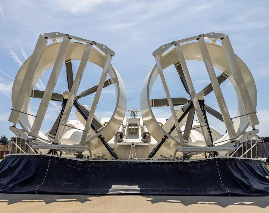
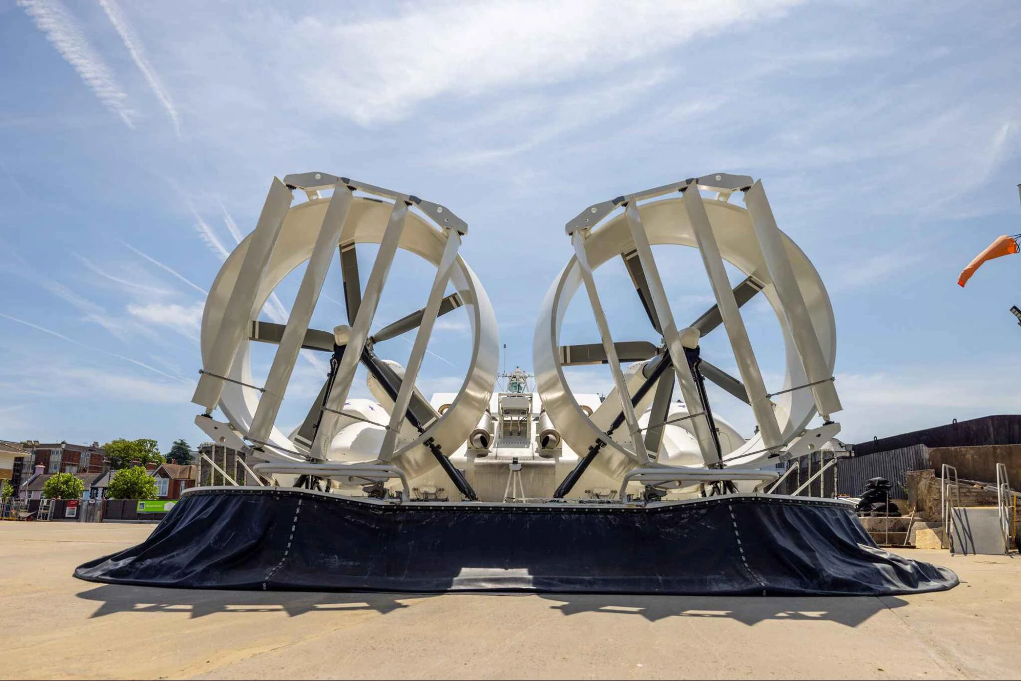
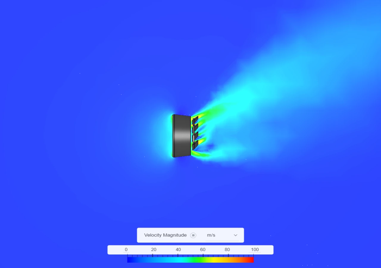
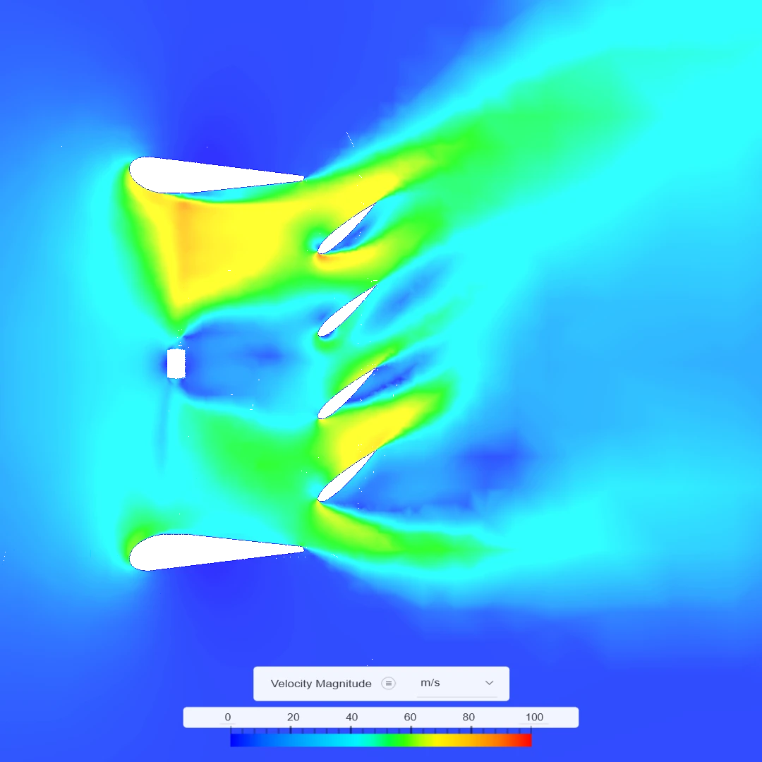
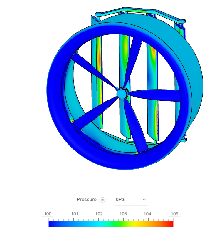
This simulation example below represents the main propulsion system on a type of hovercraft to scale. The propulsion system consists of a propeller, duct, and rudder (4 aluminum blades in cascade setup). The primary objective of this simulation was to determine the load on each rudder blade. This data is crucial for:

  • Hydraulic system design: determining the required specifications of the hydraulic system to actuate the rudders.
  • Structural analysis: performing structural strength calculations on the rudder control connection systems.
  • Flow visualization: Identifying any areas of complex flow that might inhibit aerodynamic performance.
a close-up of the propellers (5 blades rotating) and rudders (4 blade moveable aluminium rudders)
A close-up of the propellers (5 blades rotating) and rudders (4 blade moveable Aluminium rudders).
cfd flow analysis of a griffon hoverwork craft propeller
CFD flow analysis of a Griffon Hoverwork Craft propeller design showing velocity magnitude in m/s. The four aluminum rudders have an aerodynamic profile and are used to navigate the craft. Calculating pressure and loading on these rudders is a critical exercise.
A close-up CFD flow analysis of a Griffon Hoverwork Craft propeller design showing velocity magnitude in m/s. The four aluminum rudders have an aerodynamic profile and are used to navigate the craft. Calculating pressure and loading on these rudders is a critical exercise.
a close-up of the propellers (5 blades rotating) and rudders (4-blade moveable Aluminum rudder). The image shows loading on the rudders.
A close-up of the propellers (5 blades rotating) and rudders (4-blade moveable Aluminum rudder). The image shows loading on the rudders.

Benefits of Using SimScale

“Using SimScale has given us many advantages in product development. It has resulted in significant cost and time savings achieved by reducing the need for physical testing, which requires expensive components, labour and specialised facilities. The component CAD model we have can be easily changed and re-simulated in SimScale. Given the cloud-native nature of SimScale, there is no limit to the number of simulations of competing CAD variants that can be run. Since our simulations were run for a range of operating conditions, parametric boundary conditions were used. This would have been more challenging on a local computer due to limited processing power. However, the cloud-based nature of SimScale allowed us to adjust the computational resources as needed, making the simulation process more efficient. I also found that the robust auto-meshing capabilities in SimScale significantly reduced meshing time and thus simulation set-up time and, the collaboration features in the SimScale platform allowed us to seamlessly talk with the support team in the live simulation project environment.”

ayano maeda

Ayano Maeda

Systems Design Engineer at Griffon Hoverwork

Set up your own cloud-native simulation via the web in minutes by creating an account on the SimScale platform. No installation, special hardware, or credit card is required.