Cold plate cooling has moved from an overlooked detail to a core design driver because today’s systems operate hotter, denser and faster than those of previous generations.

“The moment you push performance limits, heat becomes the enemy that never sleeps.”
Alexander Fischer
Co-founder & Product Manager, SimScale
Electric vehicles depend on compact thermal architectures that keep batteries and power electronics within a narrow operating windows. AI accelerators concentrate extraordinary wattage into small footprints. Industrial automation, renewable energy hardware and medical technology all follow the same pattern.
They raise performance expectations while shrinking available space. This creates a new reality in which cold plate design becomes a strategic engineering function rather than a late stage add on. Teams that recognize this shift early gain more performance, more reliability and more control over how their products evolve.

Cold Plate Simulation in Action
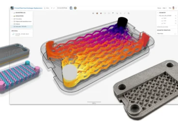
In the webinar below, we address a common engineering challenge: redesigning a battery cooling plate to maintain thermal efficiency while adapting to a new, low-power pump specification.
The Practical Challenges Facing Design Teams
Engineering teams face real constraints. They must balance:
- manufacturability,
- pressure drop,
- integration,
- weight targets,
- and routing!
You often work within tight envelopes while trying to handle rising heat flux. Parametric CAD can slow the process because feature trees resist change and complex channels break easily when edited. Conservative geometry becomes the default. This is risky as thermal loads continue to rise across industries. Cold plate cooling demands broader concept exploration, faster iteration and clearer structure throughout the development process.
 of the channel shape and baffles a cold plate to optimize the heat transfer efficiency while keeping pressure drop within pump limits")
A High Level View of the Cold Plate Design Workflow Step by Step
A typical cold plate project moves through several major steps from concept to validated geometry.
- It begins with requirement gathering where engineers define heat flux levels, target temperatures, available space, allowable pressure drop, material constraints and manufacturing options.
- Next comes the architectural exploration where macro level decisions such as cooling method, channel layout, inlet and outlet placement and flow balance strategies are evaluated.
- Concept modeling follows with early geometry that tests feasibility and identifies potential performance issues.
- Detailed design development then refines internal channels, surface area enhancements, flow paths and structural supports.
- In parallel, system level integration ensures correct fit and interaction with electronics, enclosures and the larger cooling loop.
- The final stages focus on simulation driven optimization, design for manufacturability and preparation for prototyping.
High performance applications cycle through these steps rapidly as iteration speed becomes a core advantage.

How Implicit Modeling Transforms the Design Phase
Implicit modeling fits directly into this workflow and accelerates it significantly. Traditional parametric CAD relies on sketches, constraints and feature trees. Implicit modeling uses continuous mathematical fields to define form.
Complex shapes become easy to create and sturdy during modification. Families of designs can be generated quickly without model failures. Smooth blends are inherent. Microchannels, graded thicknesses, TPMS surfaces or lattice supported walls appear without manual surfacing.
This matters because cold plate cooling often benefits from organic or highly detailed internal geometry that explicit modeling tools struggle to express.

Why Advanced Cooling Geometry Matters Now
This shift aligns perfectly with the pressure placed on modern hardware. EV power electronics keep increasing in output while packaging shrinks. AI hardware demands targeted thermal strategies that match component level heat flux. Data centers monitor every watt because cooling efficiency now affects operating cost directly. Aerospace, hydrogen systems and compact industrial machinery all follow similar trends. They require high performance cooling solutions that combine low weight, high efficiency and manufacturable complexity.
Cold plate design sits at this intersection because it enables direct heat removal and supports structurally complex yet lightweight geometries.

The Impact of Simulation and AI Assisted Optimization
When advanced modeling is paired with CAE simulation or AI driven physics prediction, the later stages of the workflow become dramatically more effective. Engineers can apply cold plate topology optimization to reshape channels for uniform thermal behavior. Microchannel networks can align with localized heat flux. TPMS or lattice structures can increase surface area while keeping weight low. Iteration becomes flexible and exploration becomes normal rather than exceptional. Cold plates evolve into highly tuned components tailored to the exact demands of each device.
Key Insights
- Microchannel cold plates deliver high surface area for extreme heat flux handling ⚙️
- TPMS and lattice structures enable lightweight internal geometries with strong manufacturability profiles 🧩
- Implicit modeling and topology optimization accelerates every design stage and supports shapes that parametric tools struggle to represent 🚀
- Simulation driven workflows improve accuracy and bridge the gap between concept and validated performance 📈
- Cold plate design has become a strategic differentiator for any product facing rising thermal loads 🔧
Cold plates are no longer secondary components. They enable the future of mobility, computing and energy systems and they reward engineering teams that prioritize them early in development.