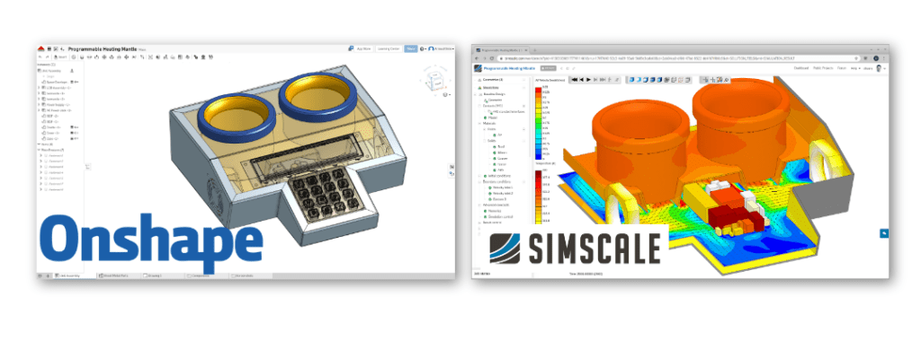
The momentum-gaining movement towards cloud-based CAE tools like OnShape and SimScale aims to let engineers do what they do best, and leave the hardware, IT issues, and collectively slow and time-consuming processes in the past. OnShape is a 3D CAD software and engineering platform, that ultimately aids and allows users to develop products in real-time. As engineers across the globe have been adopting OnShape at an accelerating rate, the adoption of virtual analysis of these designs through cloud-based simulation has paralleled success.
SimScale, striving to be the future of design validation, where engineers can easily test performance, optimize durability, and improve efficiency, works to bring the fastest analysis results to engineers, optimizing the product development process as a whole. In this article, we will demonstrate how these new-generation tools can be used to accelerate the design stage in a sophisticated workflow.
Our Case: Design Optimization of a Programmable Heating Mantle
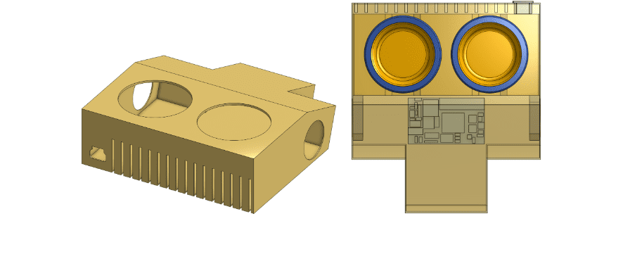
To show how you can use these tools in combination for a completely cloud-based workflow, we will explain how to optimize the design of a programmable heating mantle medical device. This equipment is typically used in laboratories to heat up containers of fluid in a homogeneous and controlled way.
The CAD model, created using OnShape, consists of different components including, casing, structural and electronics parts. The initial design is developed in order to satisfy the main design goal (heating up containers) while complying with working conditions of mechanical stress, safety, ergonomy, and thermal load in order to make sure the final product will work effectively. Once the CAD is developed in OnShape, we will then assess the thermal management through thermodynamic simulation using SimScale.
Product Development in OnShape
Using OnShape, a design engineer can digitally inspect their CAD model, the parts, assemblies, and drawings, as well as scrutinize different elements based on the design components, materials, and more. OnShape has also introduced a concept called ‘branching’, that gives visibility to different design iterations, as an innovative way to keep track of progressions instead of making file copies that then need to be stored locally.
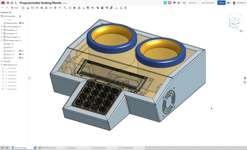
Once the design engineer is satisfied with all the components of their model, they then need to analyze it further to ensure it works as efficiently as possible in the correct conditions. For our model, the heating mantle design underwent multiple design iterations that can be seen here, until the first stage design was ready for simulation.
Thermal Analysis with SimScale
The next stage of this process is simulating the proposed model. Historically, this could only be done using costly and resource-inefficient real-life simulation, where prototypes needed to be created and tested against physical benchmarking. Then, there came hardware-based simulation, which took a large amount of computing power, expensive hardware add-ons, time, local storage, as well as other barriers of entry.
SimScale harnesses the power of the cloud to eliminate the woes of desktop simulation, while also allowing multiple designs to be run in parallel, ultimately speeding up the entirety of the design process. In our case, the multiple design iterations of the heating mantle model stored in OnShape could be evaluated simultaneously. Let’s break this process down step-by-step.
Step 1) CAD Preparation and Upload
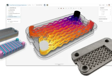
The model of the heating mantle design from OnShape had all the geometric details of the electronics board (aka, the brain and main power source of the design). We then simplified/removed the unnecessary details of this board to prepare the model for computational fluid dynamics (CFD) simulation. Holes, notches, gaps and other manufacturing features on the casing, fans, and plugs were removed.
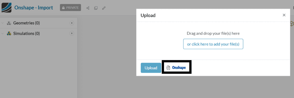
Lastly, the flow domain, representing the air volume inside the heating mantle, was modeled with a specific extension at the rear of the casing, to accurately capture the airflow through the vents. Because OnShape and SimScale work congruently and within a collaborative environment, we were able to import the simplified model directly into SimScale. Next, we identified the main design challenge.
Step 2) Heating Mantle Simulation Setup & Design Challenge Identification
Once the simplified CAD was imported into our platform, we began with an essential geometrical operation called ‘imprinting’.The imprint operation creates surface outline prints on coincident faces of two components. This creates pairs of surfaces of the same size and shape that will make thermal interfaces between components and fluid. Once this process was completed, we started setting up the simulation.
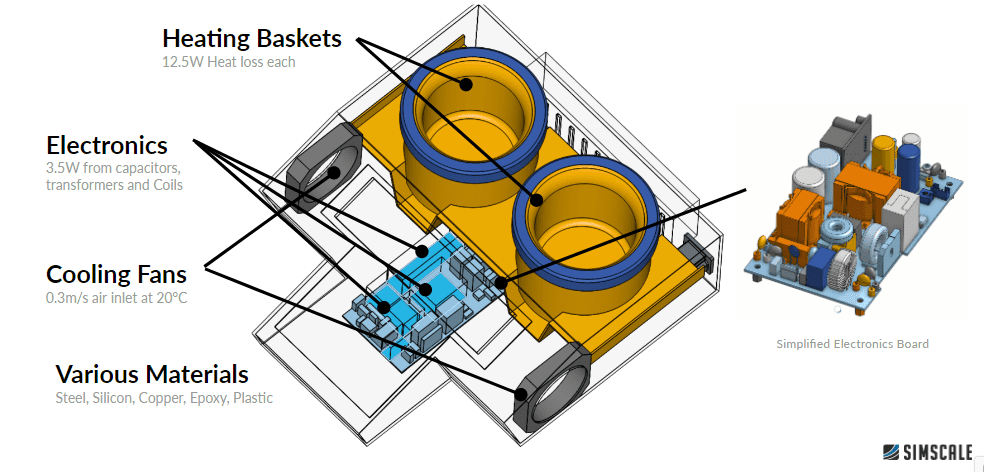
As our programmable heating mantle device was made of different components with various functions, we needed to assign materials to each of them. Each of these materials comes with different characteristics of density, specific heat, and conductivity values. These are essential parameters for evaluating thermal management of a system, as they have a strong effect on the distribution and the dissipation of the heat in the heating mantle. The thermal management challenge was established from the 28.5W of heat within the enclosure. The electronics are generating 3.5W of heat whereas each of the heating baskets produce 12.5W of thermal power.
Step 3) Thermal Management Strategy: Active Cooling
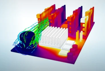
With the option of passive cooling eliminated initially, active cooling was chosen as the electronics cooling method for this design. This meant that the design strategy for cooling the components within the system was the incorporation of fans. These two fans, one on each side of the casing, were assigned a 0.3m/s inlet velocity, blowing air at 20°C.
The airflow path was directed over the electronic parts, to be then pushed toward the outlet vents. The stream of air would flow to both sides of each heating basket, and would hopefully remove heat from their surfaces.
Step 4) Analyzing Results
In order to ensure the internal components of the system do not overheat, we implemented our active cooling strategy into the simulation. Looking at the temperature distribution plot of the initial design, we can rapidly assess that 4 out of 5 critical components reach temperatures above their operating limits. Only the transformer temperature stays below the recommended threshold of 333K.
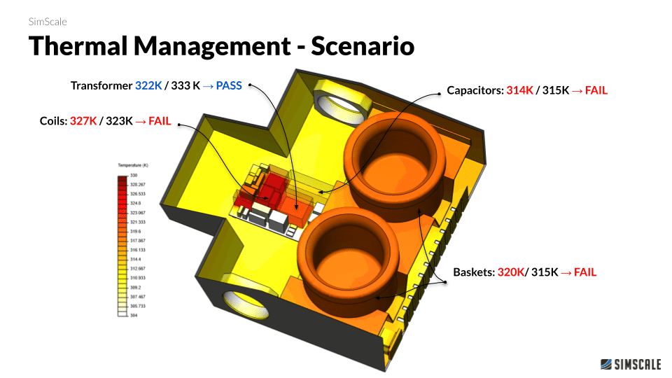
The coil component, placed in the middle of the electronic board reaches the highest temperature of all. This high-temperature value can easily be explained by looking at the airflow results within SimScale’s post-processing environment. As shown below, slower airflow around the middle of the electronics board resulted in the heat generated by the coil not being taken away efficiently and therefore shows that the initial airflow velocity was high enough for sufficient cooling.
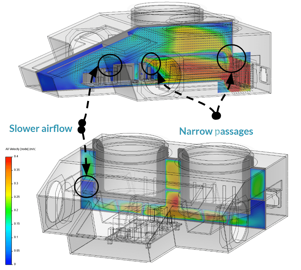
A more in-depth analysis of the flow pattern indicated that there were some narrow passages made by the cradle and the surrounding components. These created restrictions to the intended airflow path, and therefore adversely affected the effectiveness of our cooling strategy.
In addition to this discovery, it was observed that some areas of recirculation in the corners of the casing and at the upper part of the cradle also mitigated the desired effectiveness (as shown above). These recirculation effects are essentially air that swirls slowly, with little to no participation in the cooling of the components, and consequently being an energy waste.
Step 5) Design Changes to Improve Thermal Management
After having observed the two major issues affecting the cooling of the heating mantle components, namely slow airstream in the middle of the electronic board and restrictive passages generated by the cradle shape, a couple of design changes were then proposed.
Design Change One
The first proposed change was to introduce cutouts in the cradle, where restrictions of the flow have been identified.
Design Change Two
The second design change involved the extension of the vents upward by 20mm, increasing the number of vents, and rotating the electronics board. This way, the electronic board’s placement would be more aligned with the incoming airflow. Additionally, more cross-section surface area at the outlet vent could help to reduce the unwanted recirculation effects.
Step 6) Implementing Design Changes
After having rerun the simulation with these two proposed design changes, a comparative side to side result could be presented. Note that we used the exact same conditions for inlet velocity and temperature at the fans, as well as the same heat loads on the components.
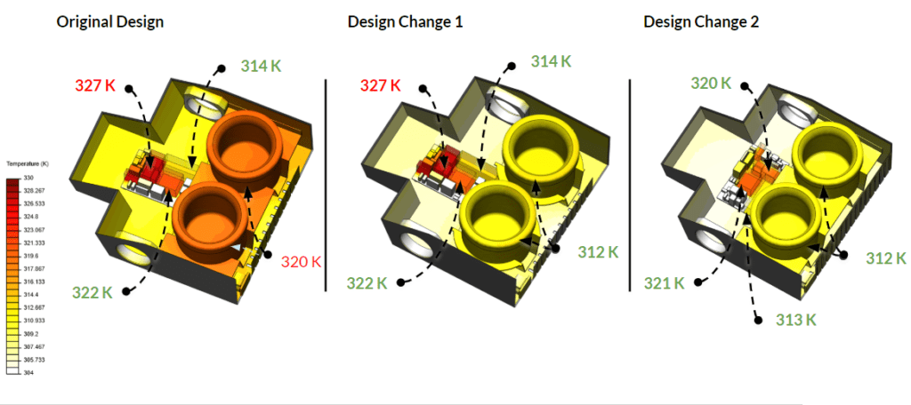
As a first observation, one can note that significant improvements could be plainly seen with the proposed design changes. The surface temperature was significantly reduced on all components by about 4°C, and most importantly the acceptable range was reached for 3 out of 4 components for the first design change, and 4 out 4 for the second design change. We were able to quickly conclude that the second design change was extremely effective in terms of increasing the airflow over the central part of the electronics board, as well as increasing cross-section area for the air flowing out of the casing.
Conclusion
This collaborative project exists as a prime example of how Onshape can be used to create and optimize a 3D design, by creating parametric assemblies and models that can then be easily made into several iterations, and then imported to SimScale for analysis as part of a seamless cloud-based workflow.
Within SimScale, we could visualize and modify the simulation setup, including assigning materials for the components, and then examine the heat load results through the integrated online post-processing tool. This, in turn, allowed us to quickly identify problems in the initial design that reduced cooling performance. From here we were able to postulate and implement a few design changes via Onshape and rerun on Simscale with minimum effort and accelerated turnover time. The result confirmed that our iterations enhanced the cooling performance, highlighting the benefit of CFD in the cloud it comes to thermal management of electronic devices.
To see the whole webinar, click here to watch now.