There aren’t many things Formula One aerodynamicists get jealous of, but one of those rare things is definitively the aerodynamical freedom of development in Formula Student. In the following article, I will introduce you to Formula Student, try to show how the above-mentioned freedom is used, and illustrate the role CFD plays in the development process.
Formula Student: Passion for the Future Profession
If you want to feel what real passion is, join a Formula Student Team. Or at least make a trip to an event. The Formula Student, or Formula SAE, named after its American founders, is an international engineering competition for students. Its target is to give students practical experience in automotive engineering and motorsports, while also promoting future engineers and innovation. Year after year, approximately 900 teams worldwide build a Formula race car from scratch, optimizing its aerodynamics.
FSAE Aerodynamics Planning, Construction, Manufacturing
Everything is made independently and unsalaried by the students and involves a lot of sleepless nights. The largest event of its type worldwide, Formula Student Germany, takes place once a year at the Hockenheimring in Germany.
Aerodynamics Aerodynamics in Formula Student
In comparison to Formula One, you have nearly unlimited possibilities in terms of developing aerodynamic devices. No standardized parts, an unlimited number of airfoils, and large building spaces allow the Formula Student aerodynamicist to design unique and sometimes extremely innovative aero packages.
Formula Student cars compete in circuits with many tight corners and without long straights. For this reason, the cars are developed to reach maximum accelerations. This means that the maximum speed of most of the Formula Student cars is around 120 kph. But in terms of accelerating from 0 to 100 kph, some Formula Student cars are even faster than Formula One cars. These circumstances dictate the main targets of the aerodynamical development.
Because of relatively low speeds and the high power of Formula Student cars, drag doesn’t affect the overall performance of the car as much as it does, for example, in endurance racing or Formula One. In most of the cases, the lap times become shorter with more downforce, even if the overall aerodynamical efficiency decreases. As mentioned above, the Formula Student circuits are full of corners. At the same time, because the speeds aren’t very high, crosswind and yaw angle can become a big factor. This means that most of the time, the aerodynamic devices must perform in situations where the car isn’t moving straight through the air.
For each event, there are four (five, if one counts ‘efficiency’ as an independent discipline) dynamic disciplines in which the car drives, namely: Acceleration, Autocross, Endurance, and Skid-Pad.
Aerodynamic Beginnings The Beginning of the Development
In the summer of 2016, the development of our team’s new car started. Having the experience of the 2016 season, we decided to do a complete restart. New monocoque, new accumulator container, all-wheel-drive with four-wheel hub motors, new aero package, and much more.
In short, we decided to change nearly everything. In this scenario, “we” means the team of eMotorsports Cologne from the Technical University of Cologne. Since 2010, the team has been building electric Formula Student race cars. Since 2015, we’ve been building race cars with wings on them. This year’s aero package is a milestone in the team’s history. Its development, which will be described in detail below, was only possible with the computational power provided by SimScale.
Aerodynamic Simulation SimScale Joins in
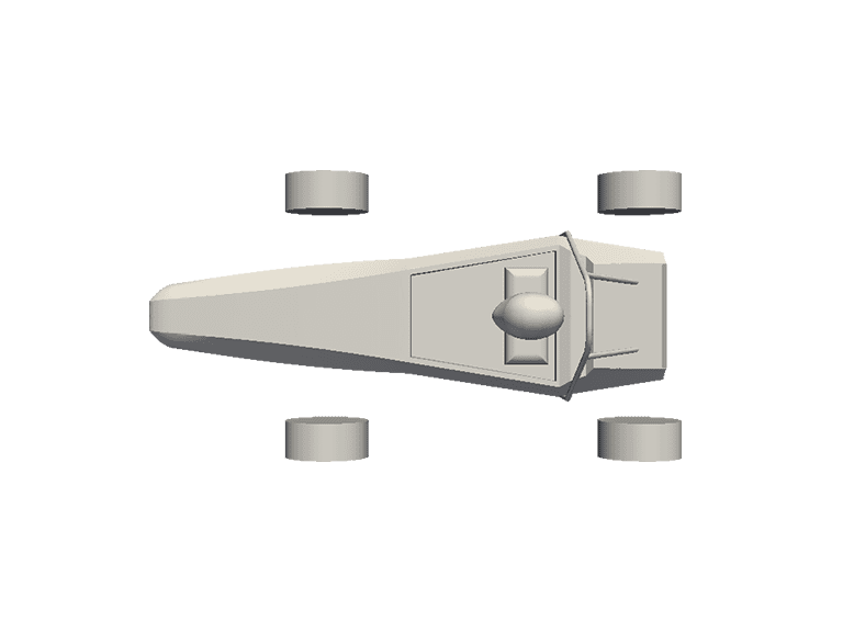
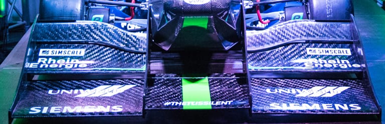
Below, you can see how the car looked like before we had the possibility to develop with SimScale. As you can see, there was nothing except for a monocoque and four tires.
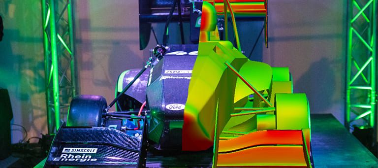
Five months and around 40,000 core hours later, this is the result of the development process with SimScale’s CFD tool:
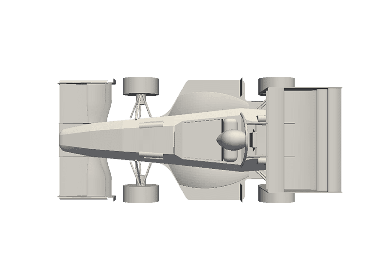
Now let’s take a more detailed look at the development of this season’s aero package.
FSAE Aerodynamics The Last Will be the First: The Rear Wing
The development started with the rear wing, which the air hits last. The reason was the massive amount of drag it causes compared to the front wing or the undertray. Because of this drag, the rear wing becomes a determining factor for the car’s overall drag and therefore the energy consumption.
After finishing a preliminary, we began to import many different airfoils into our CAD software to construct a parametric CAD Model. This was then linked with CD-Adapco’s StarCCM+ to find well-working airfoil combinations via 2D CFD analysis. The big advantage of 2D CFD is that one could simulate extremely large amounts of different airfoil combinations within a short period of time. The results of a 2D analysis are available within seconds while waiting on results of 3D CFD can take hours. But 2D CFD also has one big disadvantage: the results are rather inaccurate because the simulation is extremely simplified. 3D phenomena like pressure compensation or vortices can’t be predicted with 2D CFD.
All the preselected airfoil combinations, working well in 2D, were therefore taken to the SimScale platform to find the best-performing airfoil combination under the consideration of these 3D phenomena.
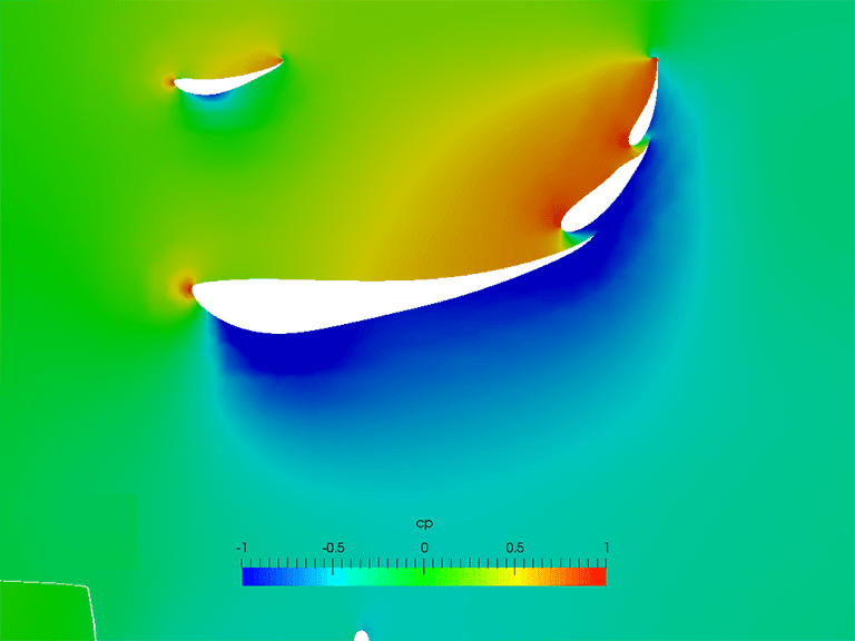
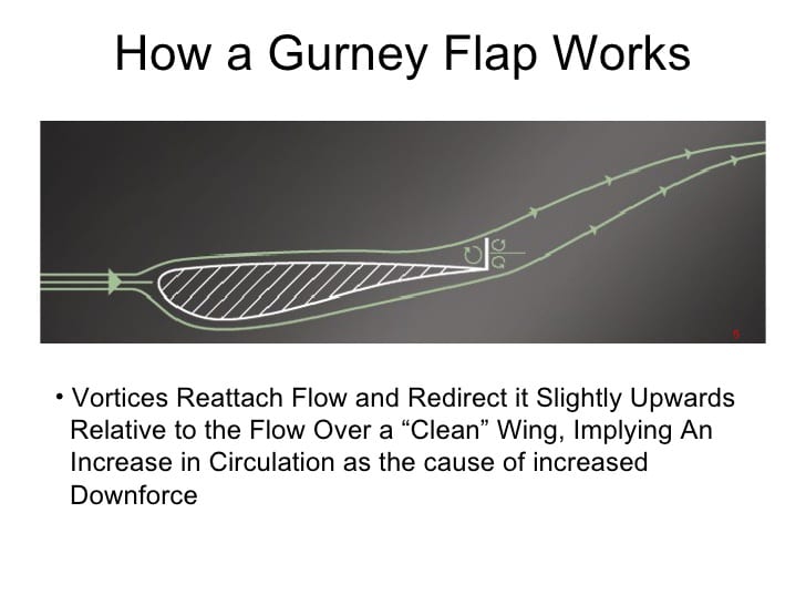
The result of the 3D simulations with SimScale’s CFD tool is a three-element rear wing with an additional leading-edge flap. To get the maximum downforce out of the wing, we have added a Gurney to the leading-edge flap and the last flap of the three-element section. The Gurney flap, which is just a simple L-profile, turns the flow upwards and forms two counter-rotating vortices behind it. These vortices help to prevent flow separation on the lower side of the wing.
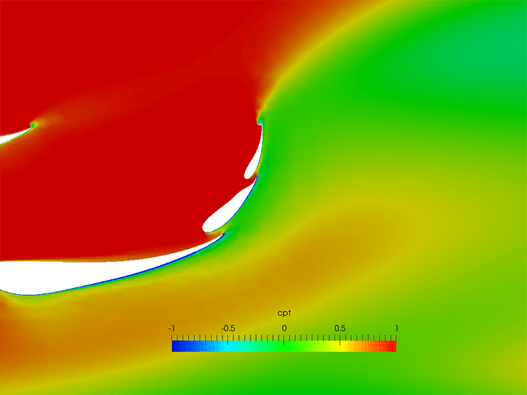
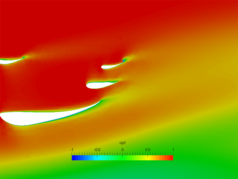
In this configuration, the wing is set up to generate maximum downforce. But hand in hand with downforce comes drag. Drag isn’t that relevant in Skidpad and Autocross, but when it comes to Endurance and Acceleration, drag becomes a factor. Therefore, we designed our flaps to be adjustable. In the picture below, you can see a total pressure coefficient plot of the same wing with different angles of attack. The drag of the wing in this setup for Acceleration is 64.7% lower than in the high-downforce setup for Autocross and Skidpad.
FSAE Aerodynamics Multitasking: The Front Wing
The front wing is the most important aerodynamic device on our car. It equalizes the rear wing in terms of balance, it guides the air to the undertray and the side pods—where the radiators for cooling are—and it also must keep the front tire’s “dirty air” region as small as possible. That is a lot of exercises for one single device, and accordingly, a significant amount of time was (and still is) spent designing it.
In comparison to the rear wing, the front wing is a lot more efficient. In our case, it is around 235% more efficient. The reason for this high efficiency is the wing’s proximity to the ground, performing in ground effect conditions. The ground and the lower surface of the wing build up a small “gap”, in which the flow is accelerated. This results in a strong low-pressure region below the wing which increases the wing’s negative lift. At the same time, due to the ground proximity, the induced drag of the wing is reduced because the ground interrupts the wingtip vortices.
The ground effect also is the reason that the middle main element of the front wing generates downforce. As it has a positive angle of attack, it would normally generate almost no downforce. But why are we doing this?
With setting the angle of attack of this element positive, we ensure that a lot of air is guided under the car into our undertray’s main tunnel (more on the undertray later).
The more interesting part of the front wing is the outboard part, which solves many of the above-mentioned problems. Next to the inner endplate, the airfoils have a reduced chord length and a small angle of attack. This ensures that enough is guided into the side box for cooling purposes.
The part next to the outer endplate in front of the tire is the most aggressive part of the front wing. The tire behind it was the reason for the aggressive design of this part because the wing should turn as much air as possible away from the tire to keep the low kinetic energy or “dirty air” region behind the tire small. Therefore, the airfoils in this location have the longest chord length and the highest angle of attack. The last flap also has a Gurney in front of the tire to turn flow upwards and keep it attached.
This target also dominates the design of the outer endplate. The endplate you can see in the picture above is an already updated version which will be installed in the car during the test phase before the events. At the end of the endplate, there is a big vertical Gurney, which turns the air outboard and away from the front tire.
The half-tube at the bottom edge of the endplate is a vortex generator which helps to “seal” the front wing from pressure compensation. Due to the pressure difference from free stream pressure to the low pressure under the wing, the flow is turned inside and the pressure under the wing increases. This pressure compensation makes the wing less efficient. But with the half-tube, the influence of this phenome is decreased. Inside the tube, a vortex, which works as a barrier, is formed due to the above-mentioned pressure difference. The flow that is turned inside must pass the vortex first before it can get under the wing. This means that the amount of air flowing under the wing from the sides is reduced. Therefore, the low-pressure region under the wing is stronger and the wing works more efficiently.
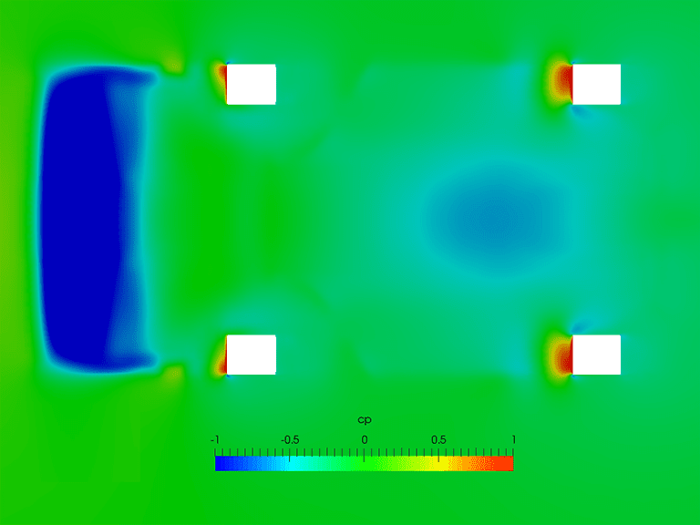
Aerodynamic Efficiency Pure Efficiency: The Undertray
The undertray is the most efficient aerodynamic device on the car. Due to its very small frontal area and the ground proximity, the undertray generates downforce without generating much drag.
Because of cost and manufacturing reasons, we decided at an early stage of the season that the undertray will have one cambered main tunnel under the monocoque and straight side plates. This is not the optimal aerodynamic solution, but the best for our manufacturing possibilities.
Nevertheless, it still increases the performance of the car. As with all aerodynamic parts, the undertray had to prove its worth in terms of performance before getting installed on the actual car. This increase in performance is proofed with lap time simulations, into which we can directly put in the aerodynamic values we get as results from the CFD simulations with SimScale.
After adjusting all other parameters that change (e.g. car weight) the lap time simulation tool calculates the best theoretically possible lap time. If this time decreases, the new part is increasing the performance and therefore becomes the new basis of development.
The major part of the undertray’s downforce is generated at the beginning of the diffuser. Even the straight side plates generate downforce.
But how is it possible to generate downforce with a plate? In front of the rear tire is a big plate, which works like a massive Gurney. The flow under the side plate is accelerated, while the pressure on top of the plate is increased. This is a rather unattractive but very simple solution to get some more downforce. A much prettier solution to improve the undertray’s downforce is a rake. A rake angle of only 1° increases the amount of downforce generated with the undertray by around 15%.
Formula Student Some Closing Words: Development with SimScale Will Continue
It is always a big challenge to develop a race car’s aero. With limited manpower, budget, and not so much experience, it is an even bigger challenge to develop aerodynamic devices for Formula Student race cars. SimScale not only provided us with computational power but also with great support in every phase of the season. We are very grateful for this support.
In the background, the development of the 2018 aero package has already started. There are a lot of things that we want to improve: the performance of the undertray for example, or the rather ineffective side of the vehicle. DRS will definitively be an option as well. It seems like there will be many changes again next year. But one thing won’t change: SimScale will play a major role in the development process one more time!
If you have any questions or comments regarding this article, the aerodynamics of our race car or the team itself, feel free to send me an e-mail to niklas.pfeiffer[at]emotorsports.cologne. We are always open to questions or any kind of suggestions!
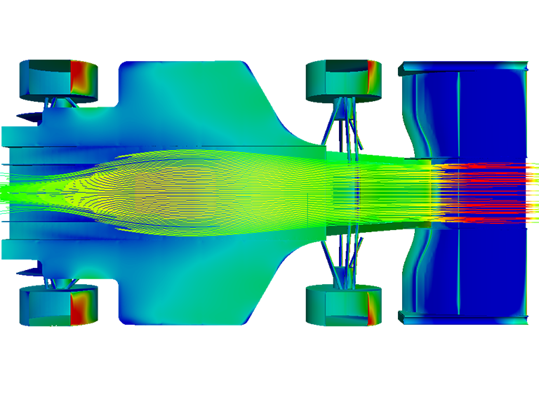
If you’d like to learn how to set up your own simulations with SimScale, you can watch this free webinar recording about the Formula One season 2017.


