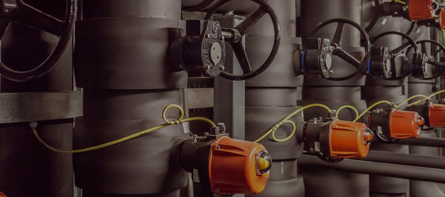
Pumps are used in many applications and industries, being a vital piece of equipment for any system that deals with water, from heating circulating flows, to consumer or industrial water supply, fountains, fire protection systems, and washing machines.
Pump Design Main Pump Types
Simply classified, pumps fall into 2 major categories: centrifugal pumps (or rotodynamic pumps) and positive displacement pumps [1].
Centrifugal pumps produce a head and a flow by increasing the liquid’s velocity through the machine, with the help of a rotating vane impeller. These pumps include radial, axial, and mixed flow units. Centrifugal pumps can further be classified as:
• end suction pumps
• in-line pumps
• double suction pumps
• vertical multi-stage pumps
• horizontal multi-stage pumps
• submersible pumps
• self-priming pumps
• axial-flow pumps
• regenerative pumps
Positive displacement pumps operate by alternating between filling a cavity and displacing a given volume of liquid. The positive displacement pump delivers a constant volume of liquid for each cycle against varying discharge pressure or head. The positive displacement pumps can be classified as:
• Reciprocating pumps — piston, plunger, and diaphragm
• Power pumps
• Steam pumps
• Rotary pumps — gear, lobe, screw, vane, regenerative (peripheral), and progressive cavity
Pump Design
Pump design needs continuous improvement in all product development stages, from concept to design, laboratory testing, engineering validation, and finally manufacturing.
Crucial in pump design is ensuring it fits the efficiency parameters. For a heating circulating pump, the total efficiency can be calculated by multiplying the motor efficiency and the hydraulic efficiency.
Depending on the pump type and size, efficiency can vary. For glandless pumps, the total efficiency can be from 5% to 54%, compared to pumps with glands for which the same factor is between 30% and 80% [3].

Pump Design Why is Simulation Important for Pump Design?
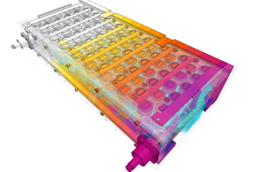
Any design and optimization process should be based on a complex set of solid mechanics, fluid dynamics, and thermal simulations. The main advantage of engineering simulation is that it allows the user to virtually test the CAD model early in the design process, and consequently iterate until finding the best possible version. As simulations can be done with a computer, the number of physical prototypes required is massively reduced.
What SimScale brings is the possibility, for the first time in history, to create these simulations in the cloud, by only using a web browser and without the need to invest in a powerful computer or licenses.
Used by pump designers worldwide, SimScale has the same web-based environment for all the simulation features, enabling one to validate experimental results, run parametric studies, and optimize designs.
Here are a few examples of pump simulation projects:
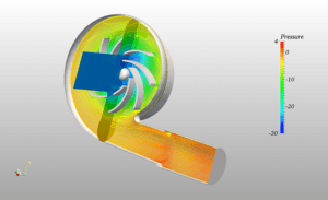
Centrifugal Pump with MRF
This is a simulation project for a centrifugal water pump using the steady state, the Multiple Reference Frame method (MRF) and the k-omega SST turbulence model.
The MRF model is one of the two approaches for multiple zones and is a steady state approximation in which individual cell zones can be assigned different rotational and/or translational speeds.
Performing MRF simulations is computationally much less demanding than transient modelling. MRF provides good approximations with less computational effort and considerably less computation time. The center of rotation, rotation axis, and angular velocity define the MRF rotation.
In this case, the geometry includes a standard backward type pump impeller and volute casing. The flow intake is done axially from the inlet pipe, exiting from the shown outlet. In addition, a separate region specifies the MRF zone in the vicinity of the impeller. For a given pump, it is vital to know the flow parameters in order to attain the accurate pressure rise. Here arbitrary values were used to demonstrate an operational example. The simulation investigates the mean velocity and pressure field in the pump.
The results, therefore, show the velocity vectors and pressure rise at the outlet for a cut section of the pump. The simulation provides insight as to how much pressure rise the pump creates for a given mass flow and rotational speeds.
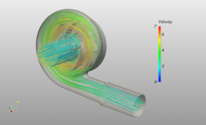
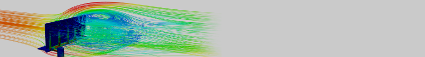
Centrifugal Pump with AMI
This project simulates a transient analysis of a centrifugal pump with a rotating mesh using the Arbitrary Mesh Interface (AMI) approach and k-omega SST turbulence model.
In the AMI approach, a mesh interface is created between the moving and stationary parts of the mesh. AMI simulations are full “Transient” and therefore are computationally much more intensive than MRF. Also, they take all transient effects into account and are usually sensitive to the time step length. In addition, AMI could be specified as oscillating or full rotating motion.
In this case, the geometry has a backward type pump impeller with a volute casing around it. The flow enters the domain from the inlet and exits from the outlet shown. An AMI zone created around the impeller defines the rotating mesh region.
The simulation analyzes the instantaneous flow in the pump. The computed results show the instantaneous velocity field and instantaneous pressure profile for a section plane. The simulation provides insight into the time-dependent changes in the flow.
SimScale’s CEO David Heiny tests the capabilities of the platform to solve a real-life engineering problem. Fill in the form and watch this free webinar to learn more!
Just upload a design and improve it!
SimScale’s Public Project library is an open collaborative platform offering different models of pumps and suggested simulations. Basic pump design simulations are available for free and any engineer or designer can copy and modify them for free:
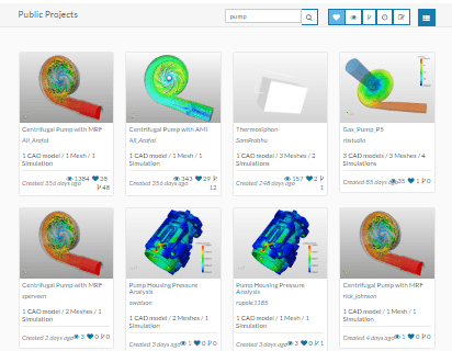
Here are a few links to some interesting pump projects in the SimScale Public Project library.
Also, I invite you to read this case study and learn how CFD technology would have helped optimize the centrifugal pump design in less time and with less effort. As simulation technology has become available to all engineers, this is definitely a step to be integrated into the pump design process.
Download this case study for free to learn how the SimScale CFD platform was used to investigate a ducting system and optimize its performance.

References
- Classifications of Pumps, Legacy Chiller Systems
- World Pumps, Demand, and Sales Forecasts, Market Share, Market Size, Market Leaders, The Freedonia Group, 2013
- Fundamental principles of pump technology, Wilo Pump Basics, 2005