This article is the second in a series of three about discovering the benefits of cloud-based simulation and the SimScale finite element analysis software in a business environment.
In the first article of this series, we discovered the benefits and advantages of the SimScale platform compared to traditional desktop simulation software. Now its functionality and practicality in a professional consulting project for the steel industry will be examined.
To give you some background, I run an engineering consulting business called Senid. One of our customers needed a structural stress analysis software of a custom-made carrying fixture, which was requested by their insurance company. The client is a steel shop that fabricates and provides maintenance for a mining company. Since large (and expensive) mining equipment and its components are being replaced, moved, and maintained, a structural safety analysis is required for all equipment and tools identified as critical. This is one of these cases.
Case Study: Finite Element Analysis Software Applied
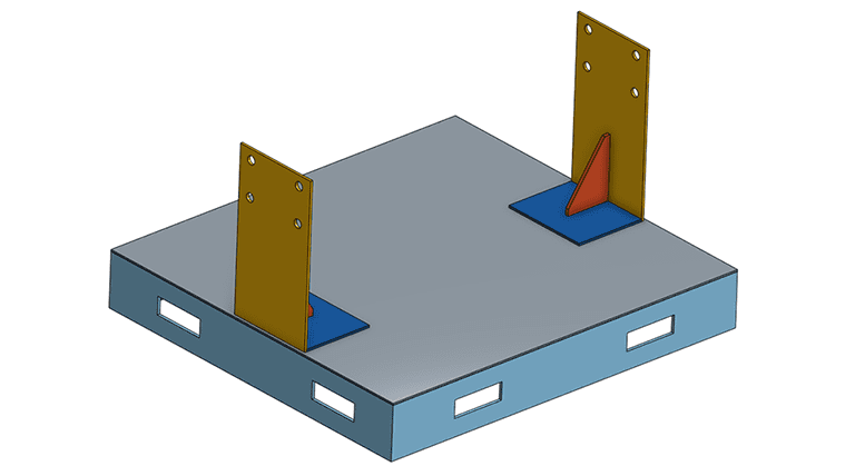
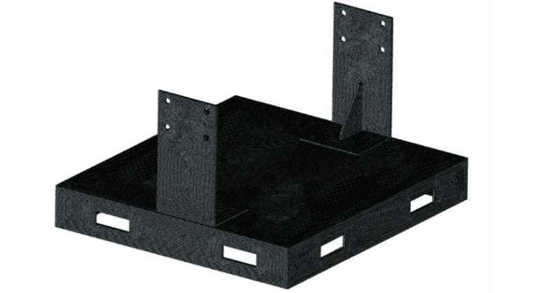
We can see the design of the structure to be studied in Figure 1, as depicted in the design drawings delivered by the client. The fixture bolts a 4 Ton piece of equipment in the upper flanges and is carried using a forklift through the bottom rectangular holes. The fixture is made of welded structural steel, plates, and channel profiles.
Modeling and Simulation with Cloud-Based FEA Software
As the structure is composed of thin-walled parts, it would be beneficial to use shell elements to model it. This would cut down on the time and simulation resources requirements. In this case, the modeling of the structure has to be done carefully to fully capture the stiffness and material redundancies in joints, and the changes in thickness. The best solution is to use solid modeling with tetrahedral elements, which makes it the reason is faster and easier to model and post-process with the finite element analysis software.
When modeling with these types of elements, some general rules are always advised:
- Use second-order elements.
- In thin-walled parts subjected to bending, use a minimum of two elements through the thickness, if first-order elements are used. One element should be enough in the case of second-order elements.
- Keep the elements’ aspect ratio close to 1.
Condition three in conjunction with condition two dictates that, if we opt for a first-order mesh, will have a very fine mesh, which goes against condition one anyway. So, we will use a second-order mesh, with the elements’ size specified, which gives us one element through our minimum thickness and maintains the aspect ratio as close to 1 as possible. The resulting mesh, computed in the SimScale platform, is shown in Figure 2.
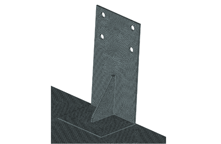
This seems to be the minimum viable mesh. in addition to this, and depending on the first results, one could identify areas of stress concentration and add local refinements. As it is, it has the following statistics:
- Number of nodes: 997 053
- Number of elements: 524 627
That is a pretty sizable problem. Running this on a typical workstation will take some time and require considerable memory resources. And that is equally true for the minimum viable model. But we won’t worry, SimScale has us covered.
The type of simulation is linear static, considering the following load case:
- 4 Ton load applied to flange holes
- Self-weight of the structure
- 2.5% lateral load, in the weak direction
- Displacement constraint on bottom holes
Simulation Results
The simulation run finished in 15 minutes with the SimScale finite element analysis software. Here is the deformation plot:
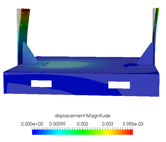
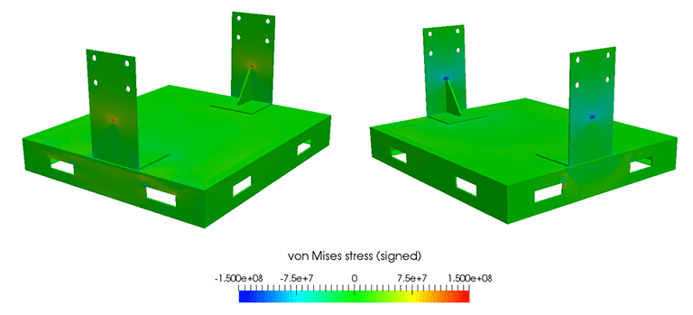
It is evident from the results that the maximum displacement is around 4 mm. Next, the stress state is examined:
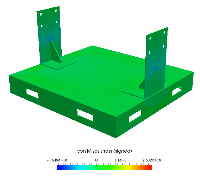
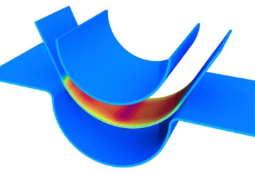
Stress concentration zones occur at the top of the reinforcement rib and in the lower carrying holes. We will take a look at the stress plot with the range clipped to the allowable stress range, to assess stress safety:
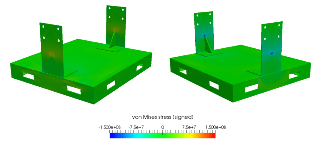
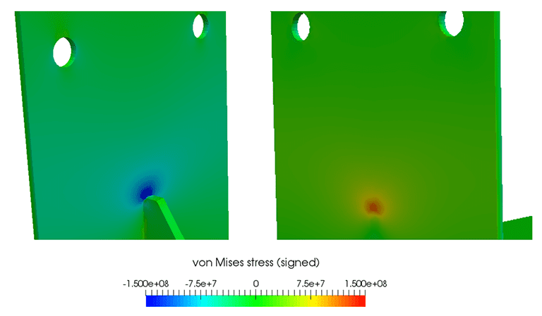
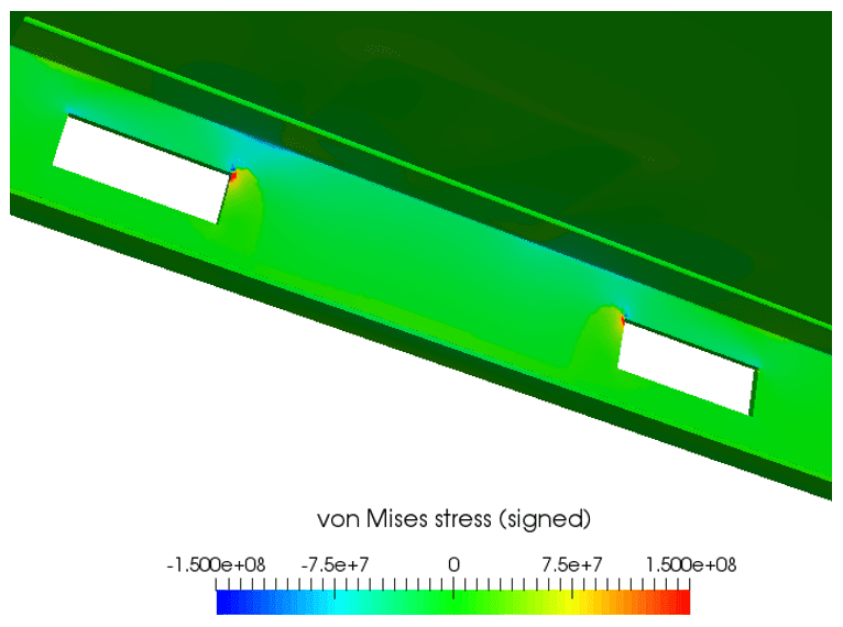
Allowable stress violation is found in two areas. The first area is the top of the reinforcement rib. The second is in the vicinity of the carrying holes. Let’s take a closer look at those areas:
With all this information, we can proceed to assess safety. As the allowable stress criteria are violated, we could directly reject the part and proceed to recommend reinforcements and plate thickness augmentation in problem zones. We could also carry out a more advanced, nonlinear simulation to analyze yielding and stress redistribution, which would provide more information for our assessment, and possibly accept the structure as it is.
Conclusion
A real-life, professional consulting stress analysis was carried out using SimScale’s finite element analysis software. Many benefits were found, such as the ability to immediately tackle a model with the recommended mesh order and refinement level, without worrying about storage, computing power, and long simulation times. In fact, the fast simulation times unlock the possibility of changing simulation parameters and models to find the best setup. It also allows the opportunity to iterate the design in a dynamic and agile manner, therefore enabling the team to meet that tight delivery deadline.
This free infographic illustrates how engineers can develop the best cooling strategy using thermal simulation. Download it for free.