Features Are Continuously Released!
As a cloud-native application, SimScale is able to continuously release new features and perform regular product maintenance on the fly. We realize that it’s often difficult to keep up with the latest news so this blog provides you with an opportunity to get up to date with all of the main new features released in Q3 2022. Enjoy!
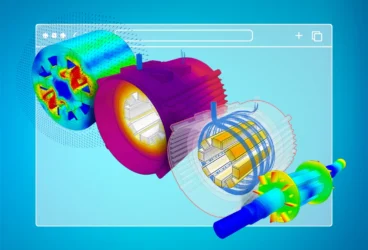
Rotational Modal Analysis
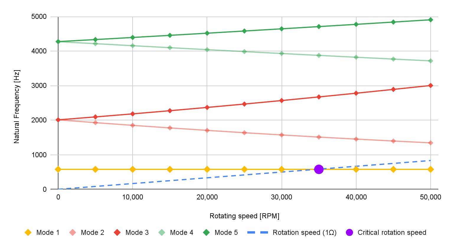
Rotational modal analyses allow users to simulate rotating shafts and take into account centrifugal forces, stiffness, and damping effects. This is important for rotating machinery applications (turbomachinery or electric machines). Users are able to export the modal analysis results to construct a Campbell Diagram to understand a component/system’s response spectrum.
- Simulates rotating shafts taking into account centrifugal forces
- Includes gyroscopic stiffness (and gyroscopic damping) effects
Use Case & Benefits
- Rotating machinery engineers looking to perform vibration analysis, modal surveys, and frequency analyses
- Accurate calculation of eigenmodes for rotating machinery
- The ability to produce Campbell Diagrams
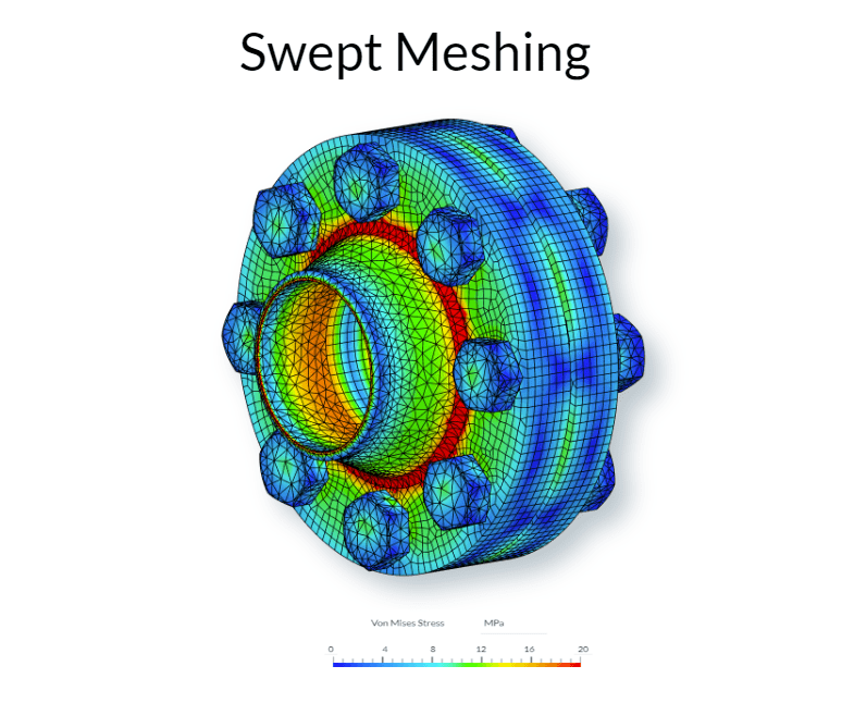
Sweep Meshing for Structural
Sweep meshing is now available for structural analysis simulations. This feature generates a prismatic mesh that sweeps between two surfaces. This feature is useful for reducing the mesh count and speeding up simulations, which saves time.
- Generates a prismatic mesh, swept from a source to a target surface
- Define element thickness and number of elements along the sweep direction
- Optionally define the absolute size of the mesh on the source and target faces
- Supports multiple source/target end face pairs
Use Case & Benefits
- Applications needing to efficiently mesh high aspect ratio shapes
- Improves meshing efficiency and solution accuracy
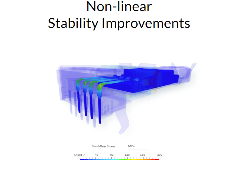
Nonlinear Stability
Several enhancements to our structural nonlinear settings have been released to improve simulation success rate/robustness with smart default numerics. Highlights include:
- User-friendly contact stiffness control, ensuring valid penalty coefficient selection for node-to-surface nonlinear contact based on contacting materials
- Reactive nonlinear solution control. This adds additional iterations, where needed, to improve simulation convergence and success
Use Case & Benefits
- Smarter default settings make nonlinear simulation even more stable and accessible
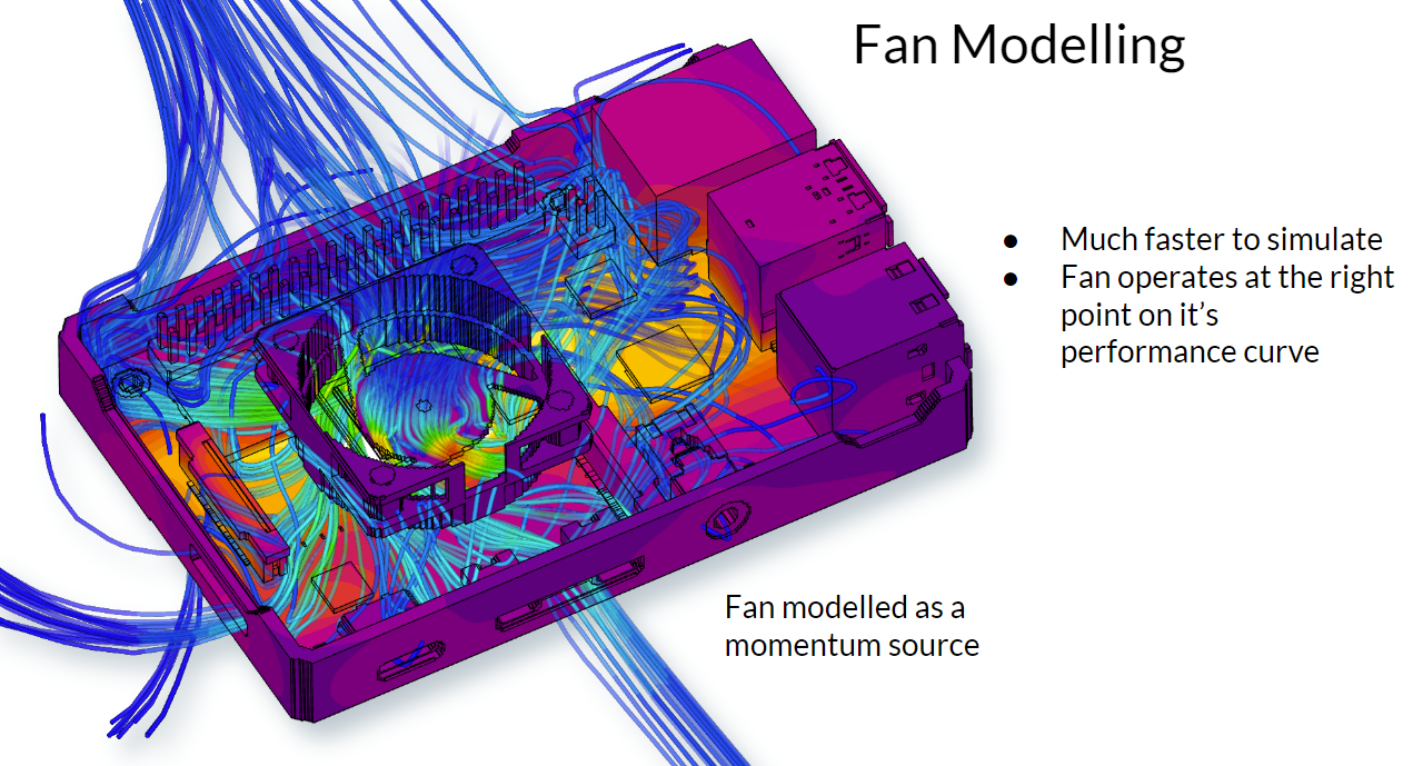
Fan Modeling
Model fans with a simple volume (momentum source), rather than needing to model the fan in detail. This is much faster than a detailed approach and a fan curve can still be applied. Fans are used extensively for active cooling in the electronics and EV/HEV industries.
- Fan Momentum Source: Allows modeling of internal fans as a momentum source that is embedded within the model
- Fan Curves: Allows modeling of fans based on fan curves (flow rate vs pressure drop). Fan curve tables can be created via table input or uploaded from a CSV file
- Fan Boundary Condition: Users can specify a Fan Inlet or Fan Outlet as a boundary condition to model fans that are placed at the edge of the enclosure
Use Case & Benefits
- Engineers who are interested in flow simulations using active fan cooling where the fan geometry is not part of the design optimization process
- Users can input fan curves from the manufacturer’s specification
- Predict the operating point of the fan
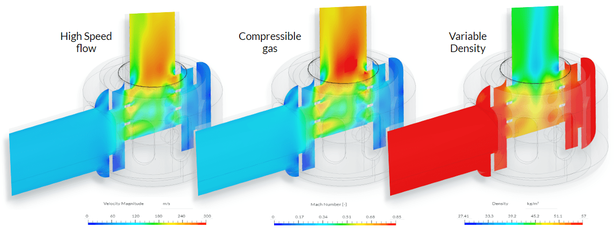
Real Gas Model
The Real Gas Model is important for accurately simulating “real” fluids that have physical and thermodynamic properties that vary as a function of temperature and pressure.
This significant new feature allows SimScale to accurately model compressors, the behavior of supercooled liquids, or the flow of steam in a steam turbine.
- Density and Conductivity are expressed as a function of Pressure and Temperature
- Users are able to input thermodynamic properties as a table, or upload a CSV file
Use Case & Benefits
- Turbomachinery and flow control simulation applications that need to model real gas effects observed at very low temperatures or very high pressures e.g., compressor modeling, supercooled liquid simulation, CO2 capture
- Allows engineers to include realistic fluid properties in their simulations, including experimental data that helps tune the simulation results to be more reliable
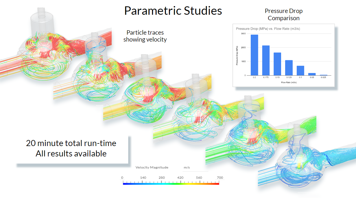
Parametric Studies
Perform parametric studies on various settings. These include the most common CFD and FEA inputs, such as velocity, pressure, temperature, power and momentum source values, centrifugal forces, and more. SimScale will run all of these studies for you in parallel.
Use Case & Benefits
- Any users who wish to parameterize boundary conditions. Examples include:
- Electronics cooling: Change inlet flow rates or heat loads on a part to understand the impact on cooling strategies
- Flow Control: Compare the performance of a valve with different inlet velocities
- Turbomachinery: Set up various rotational speeds and compare results
- AEC – HVAC: Change inlet flow rates to understand the impact on cooling efficiency
- This automated process adds value to SimScale by enabling users to quickly compare designs and understand which is the optimum
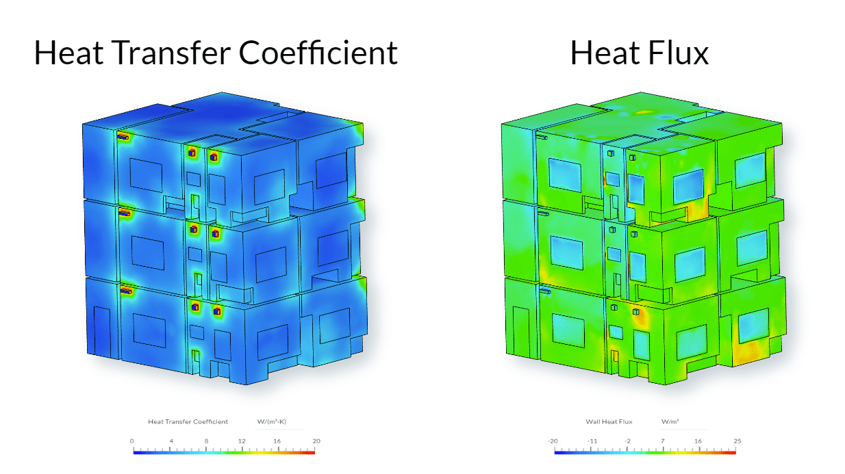
Heat Flux, Heat Transfer Coefficient, and Nusselt Number
SimScale users can now plot and measure heat transfer, a highly requested feature for applications like heat exchangers, electronics enclosures, and building design. Three results are available:
- Heat flux
- Heat transfer coefficient (HTC)
- Nusselt number
Use Case & Benefits
- AEC users that want to compute the total heat loss through walls/facade/windows — especially useful for Thermal Bridging Calculations
- Electronics designers who need to understand the flow of heat through their assembly
- Cooling or heating systems, often incorporating heat exchangers and heat sinks
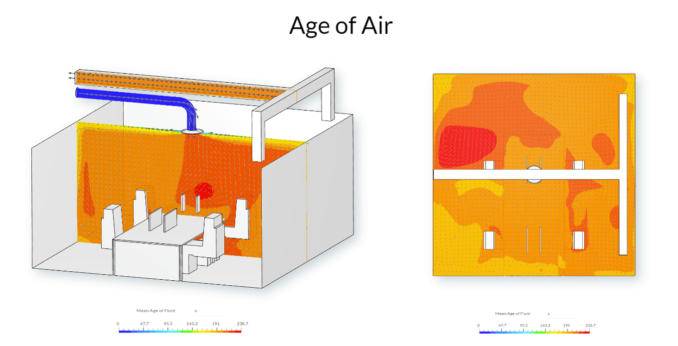
Age of Air
AEC simulation users can now calculate & visualize the Local Mean Age of Air (of any fluid) or Mean Residence Time (in seconds). Understanding the mean age of air and air exchange rates is critical when designing ventilation systems in buildings, especially for natural or mixed ventilation applications where engineers need to demonstrate that a design complies with regulatory requirements.
Use Case & Benefits
- Designers of indoor ventilation strategies where Mean Age of Air and Air Exchange rates are common design goals and even needed for compliance — in schools or factories for example
- Users can easily assess and compare age of air across different design strategies
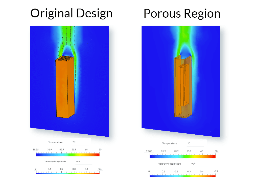
Porous Media
This porous media feature allows the simulation of partially permeable materials. It was developed to make it easier and faster to model lattices, grids, or perforations that would normally be represented as 3D solids but are challenging to mesh due to the level of detail present. This feature can also be used to model dense filter materials.
Use Case & Benefits
- Reduces the effort needed to simplify CAD geometry and reduces meshing effort & mesh size, in turn reducing simulation time. Overall a much easier process for users.
- The exact flow through these regions is usually not important, but the correct modeling of pressure drop and how it globally affects the flow is.
Take These New Features for a Spin Yourself
All of these new features are now live on Simscale and just one browser window away from you! If you wish to try out these new features for yourself and don’t already have a SimScale account then you can easily sign up here for a trial. Please stay tuned for our next quarterly product update.