What is Joule Heating?
Joule heating is an important phenomenon to capture in the design of many power electronics products and components. It is the physical effect of current passing through an electrical conductor and converting to thermal energy, causing heating. Increasing temperatures in the conductor material can impact the overall efficiency of the components or even be harnessed.
SimScale has launched new features that enable engineers to perform Joule heating simulations on the platform using an easy-to-use interface with powerful and automated post-processing features.
Simulating Joule heating is necessary for numerous industry applications where resistive heating is a common artifact, whether that is intentional or unintentional. For intentional usages such as electric heaters and soldering irons, Joule heating analysis is necessary to optimize the heat output of the device.
More commonly, however, the increase in temperature from converting electrical energy into thermal is an unwanted effect that could decrease the overall efficiency of components. Examples include busbars and wiring in power electronics, where the efficiency drops with the inverse of increasing temperature.
A similar effect is observed in batteries that have an ideal operating temperature range. Above this, the battery performance and lifetime begin to degrade. Other common components like fuse blocks and resistors are also impacted by Joule heating.
Joule Heating Analysis in SimScale
Simplified approaches to Joule heating analysis included adding dissipated power as a power source on the electronic components. The dissipated power was based on hand calculations, approximated, and could not robustly handle situations where the current density was not uniformly distributed, including:
- Varying electrical resistivities in parallel
- Different cross-section-sized components in serial alignment
- Contact resistances, for example, soldering connections
With the new features introduced in SimScale, users can now explicitly define the key Joule heating parameters, variables and output key metrics to base design decisions on.
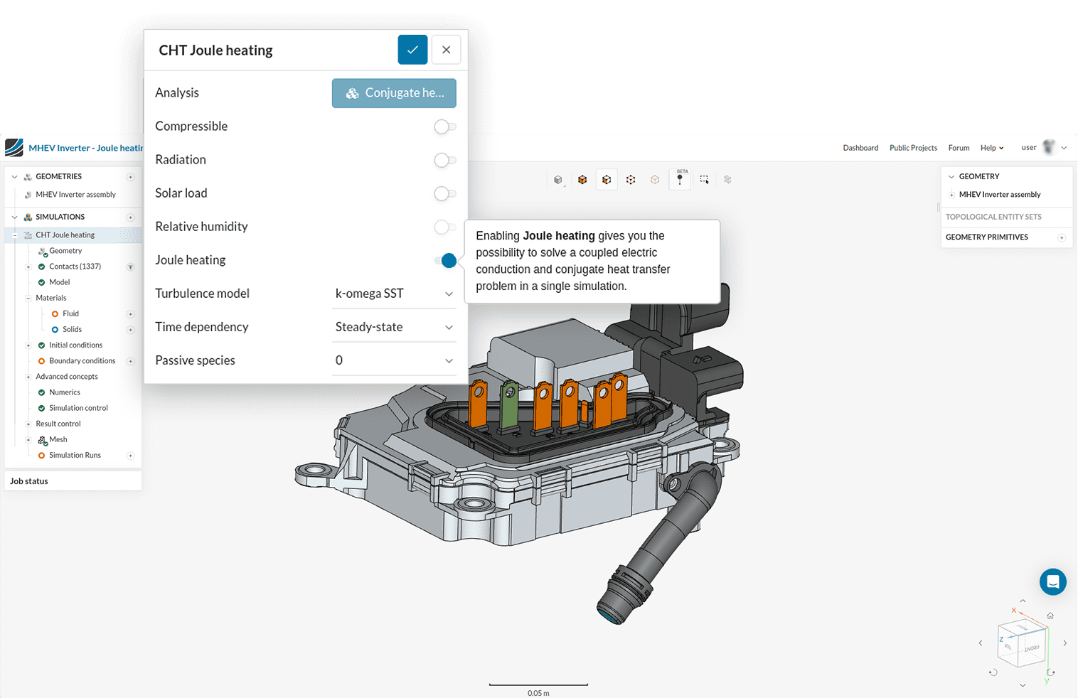
- Analysis type: users can toggle on Joule Heating when setting up a Conjugate heat transfer (CHTv2 or IBM) analysis type in SimScale.
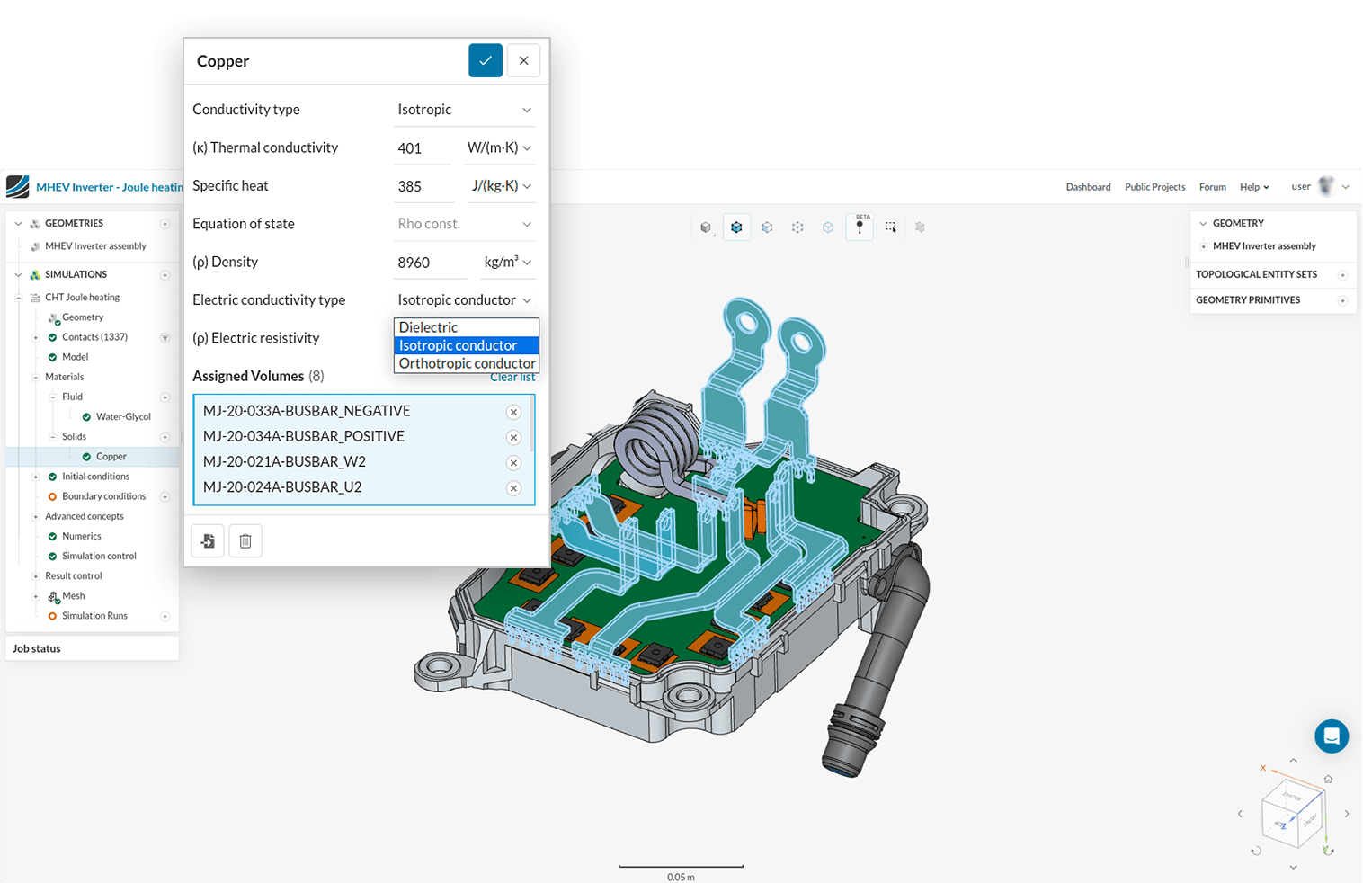
- Materials: when defining material properties, choose the isotropic or orthotropic conductor option. The materials can be imported from the library or added to the database and can be shared among projects and teams.
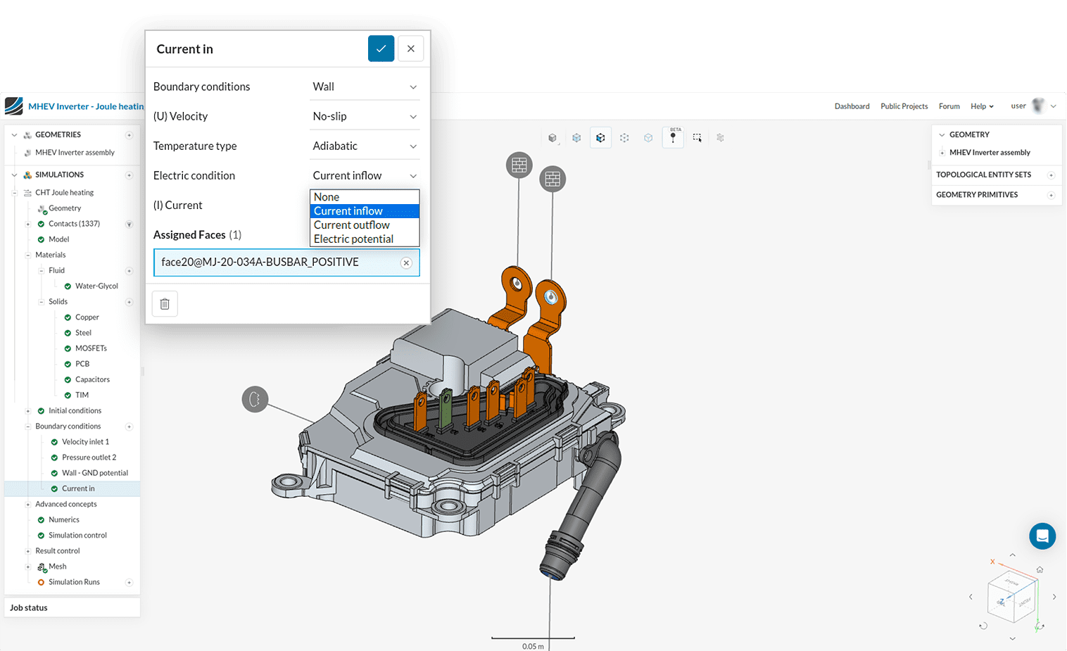
- Boundary conditions: in the boundary conditions dialog box, users can specify the current flow direction and electric potential (see images below).
- Outputs: include current density, electric potential, and Joule heat generation.
Joule Heating Simulation Setup
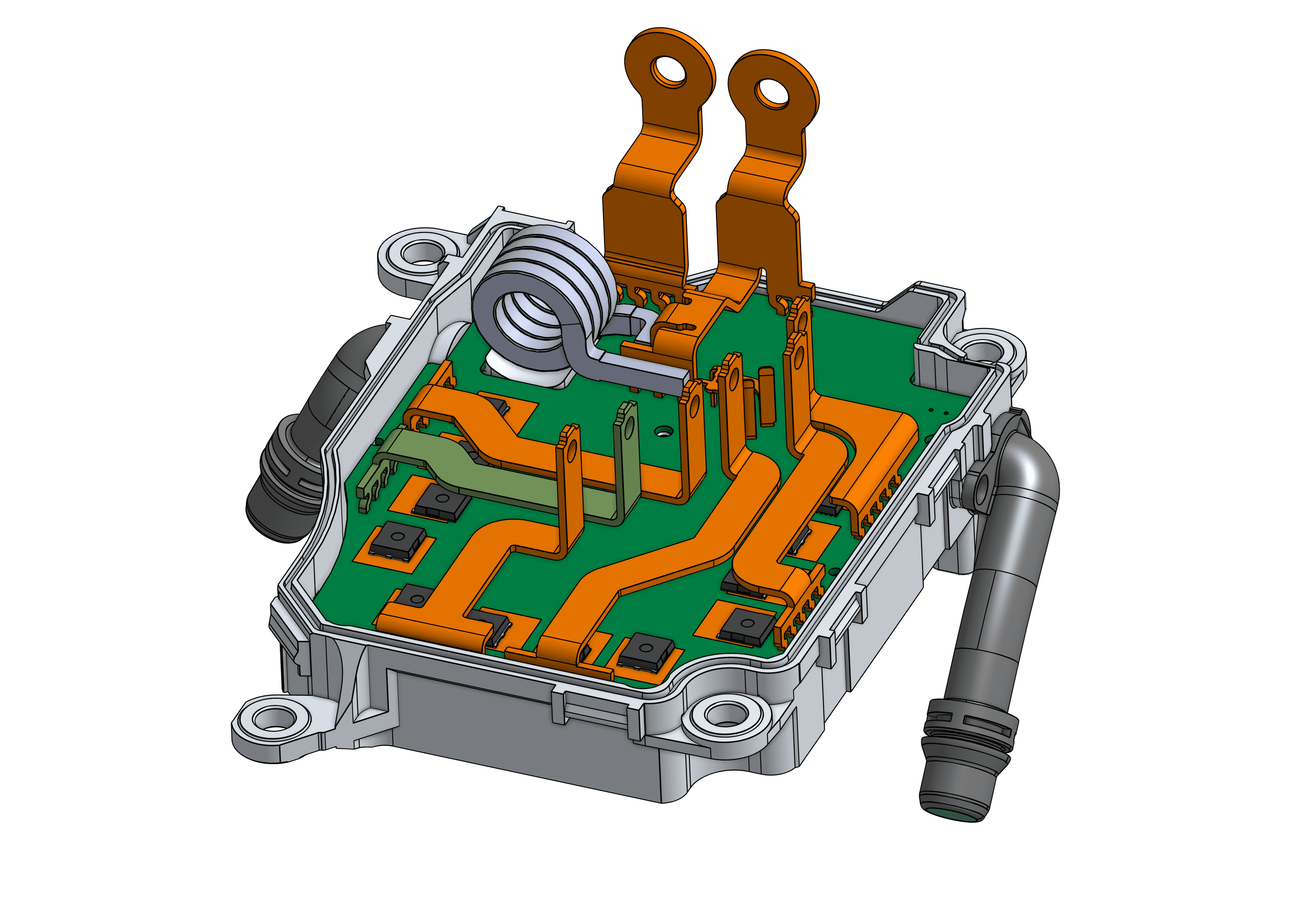
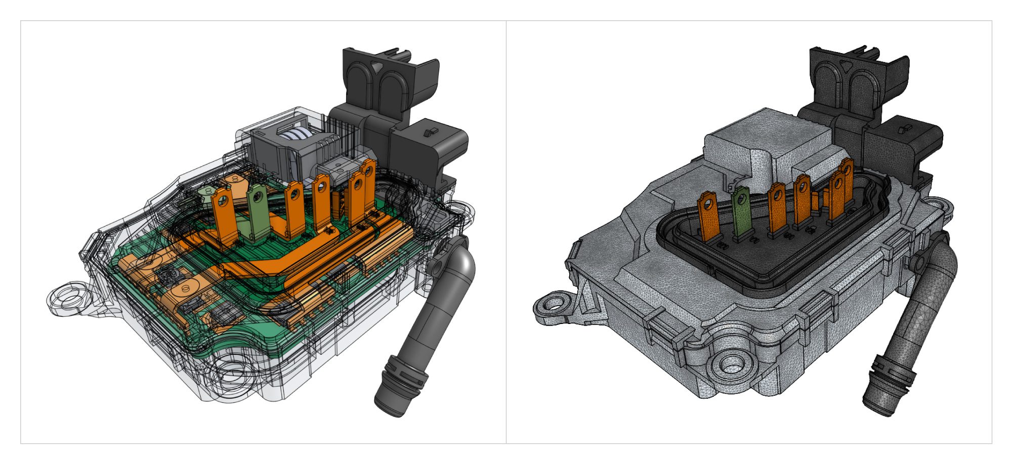
A case of an electrical inverter used in race cars is used to demonstrate the new Joule heating features in SimScale. The image below shows the 3D geometry of an inverter that is liquid-cooled using a water and glycol mix with a flow of 3 L/Min.
The model contains various MOSFETS and capacitors with electrical load and current of up to 70 Amps RMS continuous load. The twelve MOSFETS for 6-phase AC current supply are each modeled with 18.5 W applied to them.
We have used the materials database in SimScale to apply conducting materials and coolants that can be parameterized to evaluate material properties if needed.
New options in the simulation setup dialog boxes are used to specify Joule heating simulation particulars:
1. Specifying Joule heating analysis
2. Material properties for Joule Heating simulation
3. Adding boundary conditions for Joule Heating simulation
Visualising Joule Heating Simulation Results
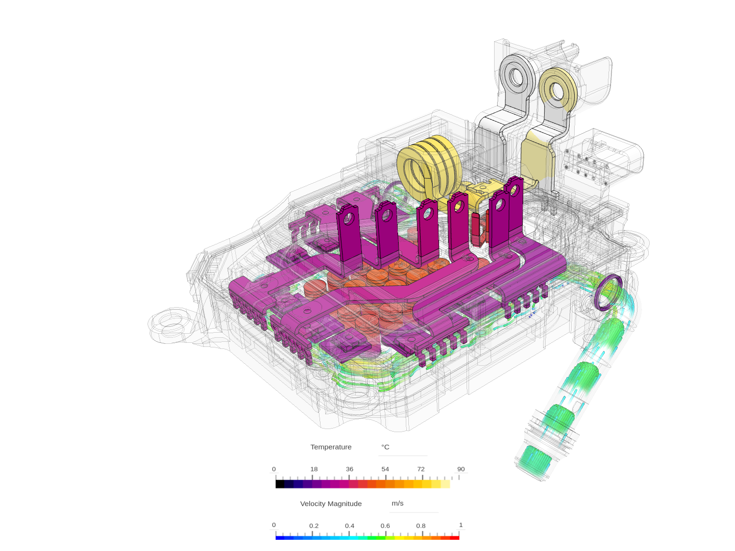
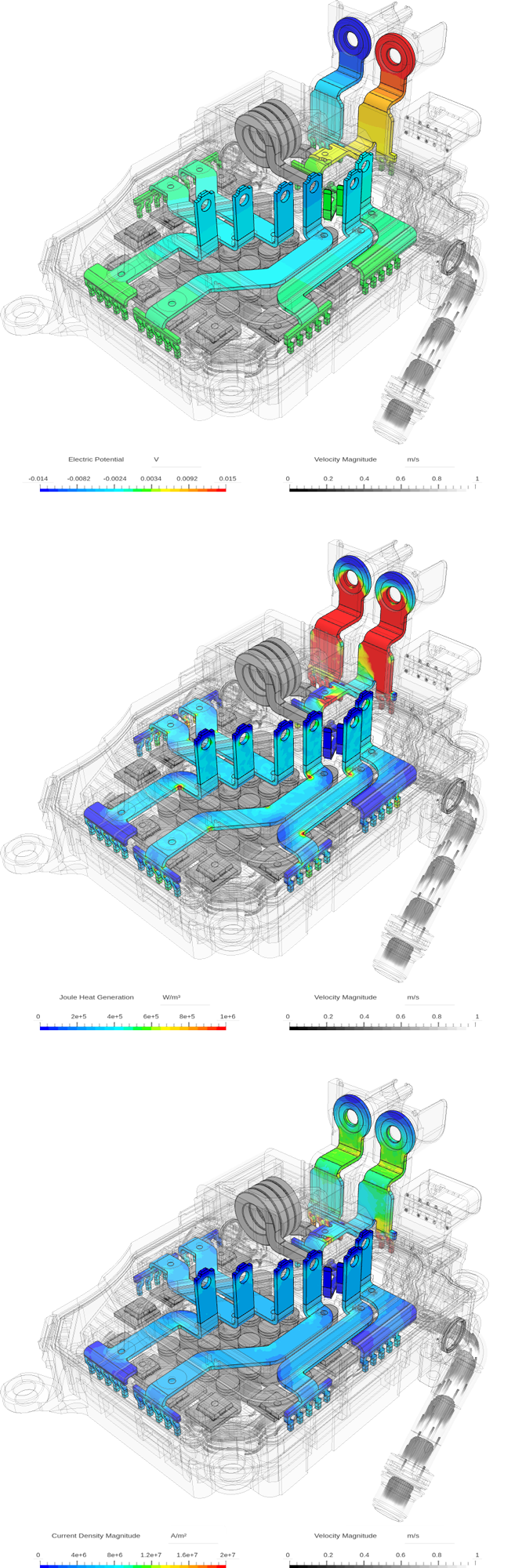
The Electric Potential (voltage) gives insights into the voltage drop across electrical components and wires within the electric circuit and the expected voltage drop overall in case of a current drain-driven simulation. Derived from the electric potential field, the electric current density (A/m2) provides essential information about the electric current flow in the whole circuit and if current density spikes occur, e.g., in small cross sections or at sharp corners.
Those often lead to high thermal losses as the dissipated power depends on the electric current by the power of two. This information can be used to thicken the cross sections at critical spots or change the overall current path by rounding off unfavorable edges.
The Joule Heat Generation (W/m3) result field comes in handy when judging the heat flux that needs to be considered when designing the thermal management solution for the system. Even if the Joule heating contribution is not the main thermal load in the system, it can harm the overall performance or reliability of the product if local heat flux spikes happen distant or shielded from the main cooling solution, e.g., a liquid cooling plate or a fan.
Using the statistical tools in the Post-Processor, one can extract both the distributed heat load as well as the integrated total power loss on a part of the model.
Power Electronics Simulation in SimScale
Joule heating is essential or relevant to the design of a variety of applications. Next to the inverter use case, those include other components of the electric powertrain in electric vehicles such as the battery pack or electric motors. It is also the most important aspect of electric resistor thermal considerations. In the following, we present industry-relevant examples.
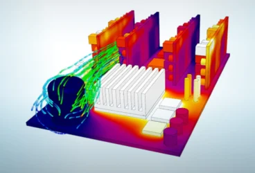
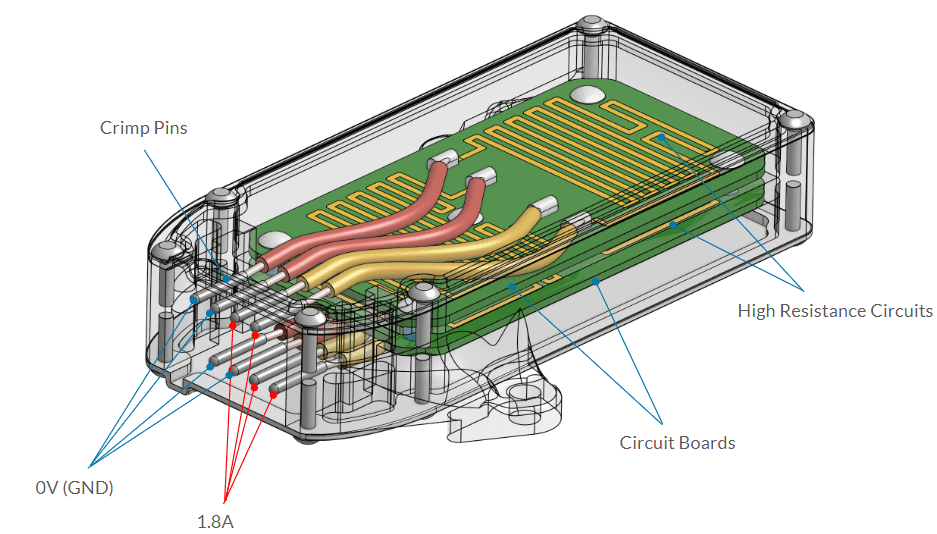
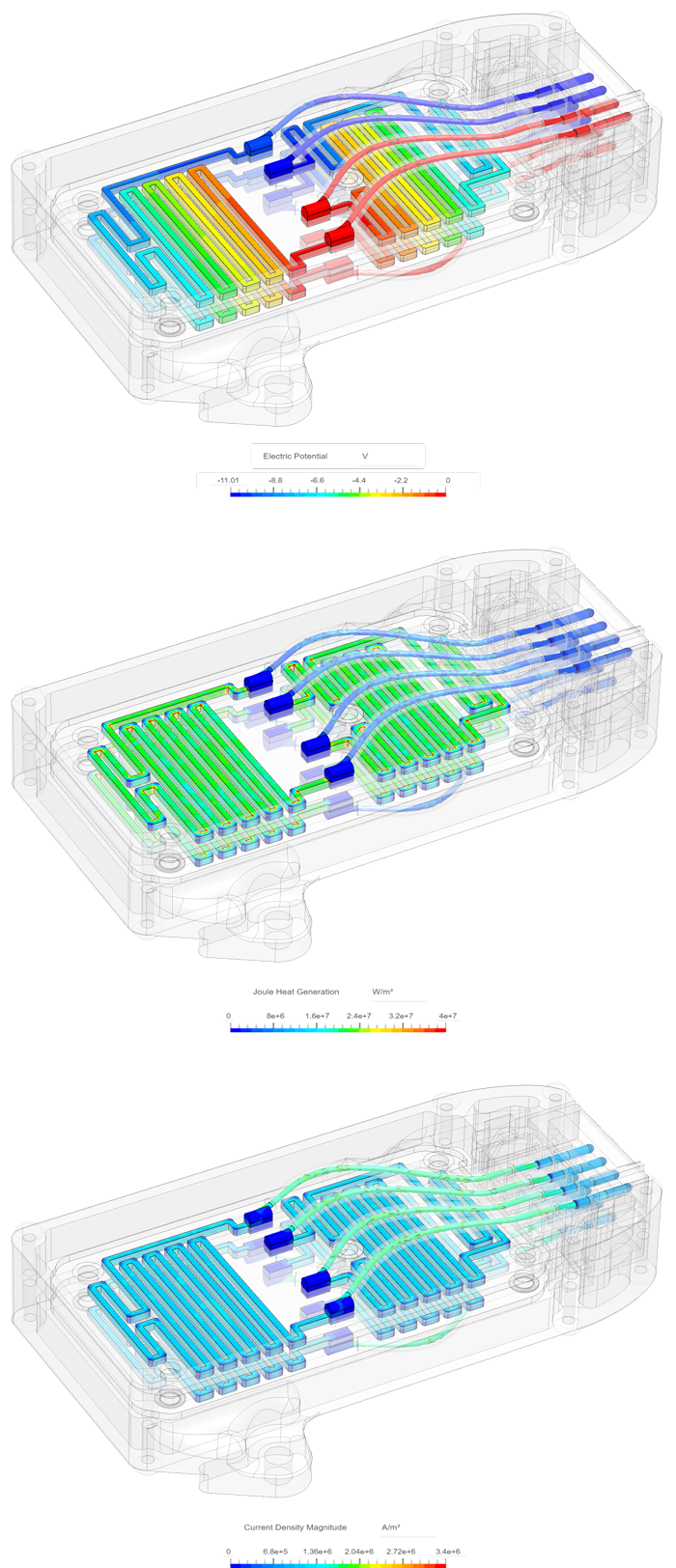
Resistors
Resistors are used to protect other components in an electric circuit with high voltages or current pulses using highly resistive materials, ideally in a compact structure. While the potential drop and the resulting heat conversion are therefore intended, the heat can still be damaging to the resistor or the surrounding system. Cooling solutions include mostly mounted heat sinks but can also involve active air or liquid cooling.
The power resistor model has four separate resistive conductor circuits and is a device that has been used in the automotive industry in the past extensively. This particular model was used in Jaguar oldtimers and ensures the electronic control unit (ECU) for fuel injection does not overload from high current spikes.
In order to open the injectors, the full 12V potential is connected and provides the required high opening current of 22.6 A. After that, the required current is much lower and the components can not withstand the high current load for long. Hence the ~6 Ohm resistor circuits are added to the circuit with a switch and reduce the current below 2A. The component is mounted at a sheet metal component next to the engine and therefore must only rely on natural convection cooling.
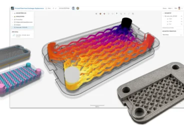
Electric Vehicle Battery
The battery module case is from an electric vehicle from the Formula SAE (Society of Automotive Engineers) race cars. Formula SAE is a series of international competitions in which university teams compete to design and manufacture the best-performing race cars and simulation is extensively used by academic teams to optimize their race car designs and components.
The battery module uses forced convection air cooling from fans for thermal management and has aluminum busbars. It has 100 lithium-ion cells in a 10S10P arrangement (10 cells in series, 10 cells in parallel).
The Joule heating analysis is needed to predict heat gain from current flowing through the battery components and test optimal cooling strategies. Analyzing the electric potential drop and current density is additionally helpful in order to avoid current spikes at sharp corners or thin sections and aim for a uniform load across the pack. In this case, a 1C scenario is simulated with 40 Amps drained from the module.
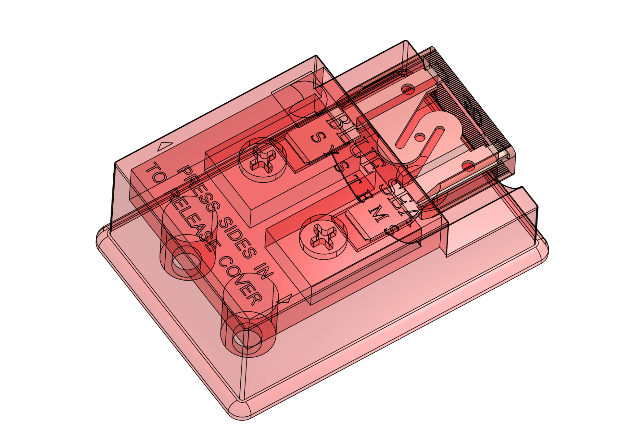
Fuse Blocks
The following fuse block case is widely used by automotive Original Equipment Manufacturers (OEMs). Fuses operate under a small potential difference, allowing current to flow within the fuse. As long as the current remains within safe limits, the fuse functions normally.
However, fuses are designed to serve as intentional weak links in electrical circuits, such that they sacrifice themselves by failing at their weakest points to protect expensive or sensitive equipment from high current values. The failure of a fuse occurs due to heat generated by current flow at its weakest points, which may result in local melting around those regions.
To simulate the operation of a fuse and be able to observe the temperature rise around the weak regions, a transient conjugate heat transfer analysis is used with the potential difference between the two ends of the fuse being set. In this scenario, a potential drop of 0.2V was applied to the fuse with a resistance of only a few milliOhm resulting in a huge overload current with the highest current density around the weak point.