Creating a high-quality mesh is one of the most critical factors that must be considered to ensure simulation accuracy. It is important to note that there are significant distinctions between meshes created for two of the most common simulation areas—computational fluid dynamics (CFD) and finite element analysis (FEA). This article will provide some quick tips for improving your mesh quality and hence increasing the quality of results for simulations carried out with the SimScale cloud-based platform.
Meshing on SimScale is done with snappyHexMesh—a mesh generator that “builds” meshes iteratively on your geometry. As mentioned by the OpenFOAM wiki, “snappyHexMesh is more of a mesh sculptor than a generator, because it requires an already existing base mesh to work with”.
SimScale offers four primary meshing methods:
- Tet-dominant
- Hex-dominant automatic (only CFD)
- Hex-dominant parametric (only CFD)
- Hex-dominant automatic “wind-tunnel/external flow” (only CFD)
Of the four meshing methods, the hex-based meshers are only for use in CFD, while the tet-dominant method can be applied to both CFD and FEA. The tet-dominant method is typically used in 3D meshes where the robustness is more important. Although quadrangular surface elements are an option, sometimes errors may occur if the option is enabled.
The remaining three hex methods, as you can guess, are only used for CFD meshes. Both of these automatic hex methods provide a simple and effective way to quickly create a mesh that can be easily adjusted for fineness depending on the usage of external or internal flow. However, in order to achieve the quality level that most accurate simulations require, the highly customizable hex-dominant parametric is the preferred option.
Although generally valid for mesh generation, the tips below will particularly apply to the hex-dominant parametric method.
Sign up & check out our SimScale blog for much more!

Importance of an Accurate and High-Quality Mesh
As a good mesh is the basis of an FEA or CFD online simulation, it is important to understand exactly why ensuring its accuracy and quality is critical.
A common question is: “If I want a better mesh quality, can’t I just increase the fineness level to as high as possible?” While increasing the fineness will typically yield a higher quality mesh, the computational cost will significantly increase as well. A high-quality mesh also means that there is an optimal balance between the computational cost and the level of fineness achieved.
A low-quality mesh will not only result in inaccurate simulation results but might even cause the solver to produce an error due to instability. Such instability is typically caused by poor-quality or illegal cells. This is something you want to avoid as much as possible. Likewise, while a mesh may contain millions of nodes, that fact alone does not necessarily equate to quality. Such quirks in meshes are case-specific and will not be covered in this article.
5 Tips on How To Create a Better Mesh
That being said, let’s cut to the chase. Here are five tips on how to create a better mesh and ensure the accuracy of your simulation results.
1. A Simplified and Clean Watertight Geometry
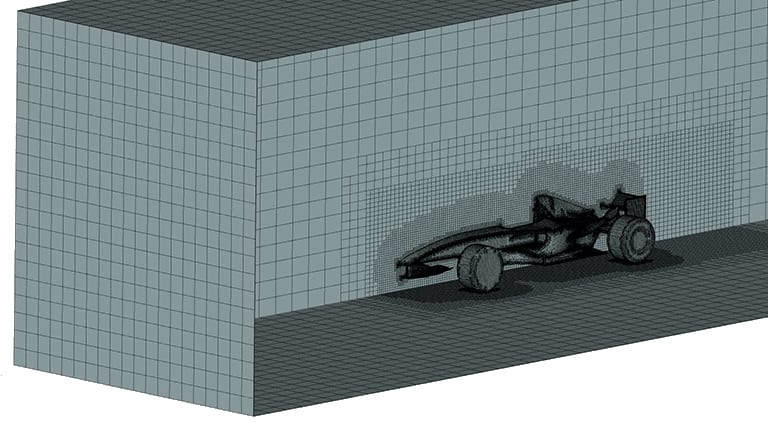
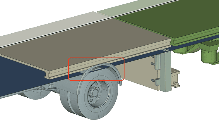
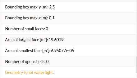
Ensuring a well-defined, simplified, clean and critically watertight geometry will often be the difference between a successful high-quality mesh or a poor, illegal, cell-filled one. Geometries should be solid and have no abnormal features such as intersections or sharp outcroppings. A clean geometry dictates that it is enclosed and is free from geometrical defects. The creation of a watertight geometry will allow the solver to differentiate between different domains of flow, which is very important, especially for external flow simulations. This can be checked natively on SimScale.
2. Deciding and Maintaining a Good General Grid Size
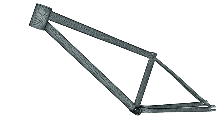
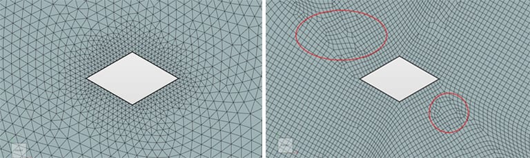
In general, maintaining the skewness ratio of the cell is key to accuracy and quality. For complex geometries, maintaining the skewness ratio of every cell may be difficult, if not impossible, it is best practice to ensure that it is closely adhered to. Different cases require and dictate different skewness ratios, but for general usage, a strong cell distortion is often an indication that the skewness ratio of the cell is too large and further refinement is needed. Notice the figure below: while this is a tetrahedral mesh, you can easily see which one is of a lower quality.
For the hex-parametric meshing method, maintaining an overall grid size that keeps the skewness ratio low is a simple but effective way to increase the accuracy. This can be done by first selecting the intended cell size via literature or referenced works before the domain distance is calculated and divided by the number of cells.
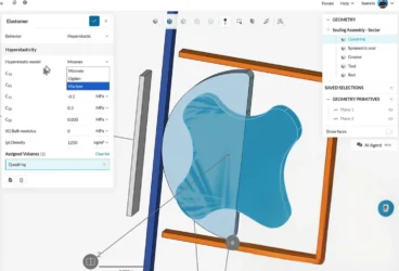
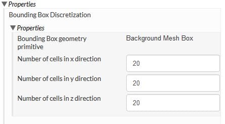
For example, if the user requires a cell size of 0.5m for a 10 by 10 by 10 m domain, the user then needs to take the length of each domain, divide that by the cell size and then input the results into the mesh operations tab shown below for all lengths in order to maintain the skewness at 1—which is ideal.
3. Increasing Mesh Fineness at Critical Areas
This tip ties into the balance between computational cost and mesh fineness. Say you have a specific general cell size to maintain, but you require additional accuracy near critical parts that, if adjusted through overall cell size, would be much too computationally expensive to simulate. A way to get around this would be to designate the area at or around the critical part with a higher refinement in that particular region. This effectively decreases the cell size of only the target area but does not increase the computational cost dramatically.
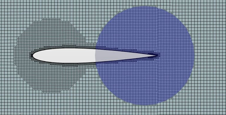
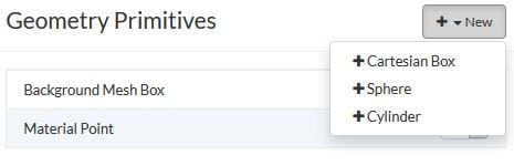
This method can be applied to further increase the accuracy of the simulations that have not opted to do so and is often used in applications like wake prediction or vortex generation. To perform this with SimScale, a geometrical box needs to be created first and then a region refinement applied to that geometrical box.
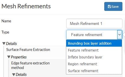
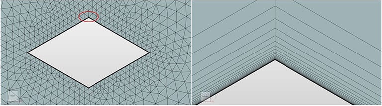
4. Boundary-Layer Refinement and Y+
Boundary layer refinement or inflation is a critical meshing parameter that is sometimes overlooked by those who are new to CFD online simulations. While effectively increasing accuracy near the internal or external surface of the geometry, the boundary layer refinement also, more critically maintains the dimensionless wall distance value or Y+ for the chosen turbulence model in order to increase accuracy. Y+ is a key factor that ties in directly with the turbulence model used. For example, using the k-w SST model often dictates a Y+ of less than 1 in order for the mesh to capture the wall effects.
Numerous websites provide a simple calculator that will allow the determination of the smallest layer near the geometry for a given Y+ value. Such websites include Pointwise and cfd-online, with Pointwise providing a phone application that can be downloaded to calculate Y+.
5. Mesh Convergence Study
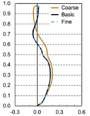
The final tip concerns optimizing and determining the ideal mesh to be used for further simulations. A mesh convergence study dictates that a general mesh is created for the problem case, a simulation is run, and the results are obtained. Afterward, the process is repeated with a continuous increase in mesh fineness. The steps are repeated with ever-increasing mesh fineness until the results obtained deviate to a range of less than 1% to 5% depending on criteria.
Once the results have deviated within the required criteria, the coarsest mesh produced that is still within the criteria is deemed the base mesh and, as such, the results obtained are then as accurate as possible for the given mesh.
A proper mesh convergence study will not only ensure that your mesh is as accurate as possible, but that is also optimal. This means you are balancing computational time with accuracy, which is crucial when it comes to large and complex meshes.
Conclusion
With these five quick tips and a better understanding of SimScale’s meshing options, as well as insights into why mesh quality is so important, your meshes should have a considerable increase in quality and accuracy. This not only leads to better convergence, but also more accurate results from your simulations. While this article does not cover all the criteria that need to be considered for a highly qualitative and accurate mesh, I hope it helped you gain some valuable insight into such a critical part of the simulation.
If you’d like to read more about meshing, you mind find this article interesting: Tips for Meshing Your CAD Model for Structural Analysis.
References
- https://openfoamwiki.net/index.php/SnappyHexMesh
- https://www.iaeng.org/publication/IMECS2009/IMECS2009_pp2165-2170.pdf
- https://www.engineering.com/DesignSoftware/DesignSoftwareArticles/ArticleID/9296/3-Criteria-for-Assessing-CFD-Convergence.aspx
- T. V. Hooff, B. Blocken and Y. Tominaga, “On the accuracy of CFD simulations of cross-ventilation flows for a generic isolated building: Comparision of RANS, LES and experiments,” Building and Environment, p. 18, 13 December 2016.