Link to part 1 of the tutorial:
Step-by-Step Tutorial Session 3 - Yaw Angle Study (Part 1)
Introduction
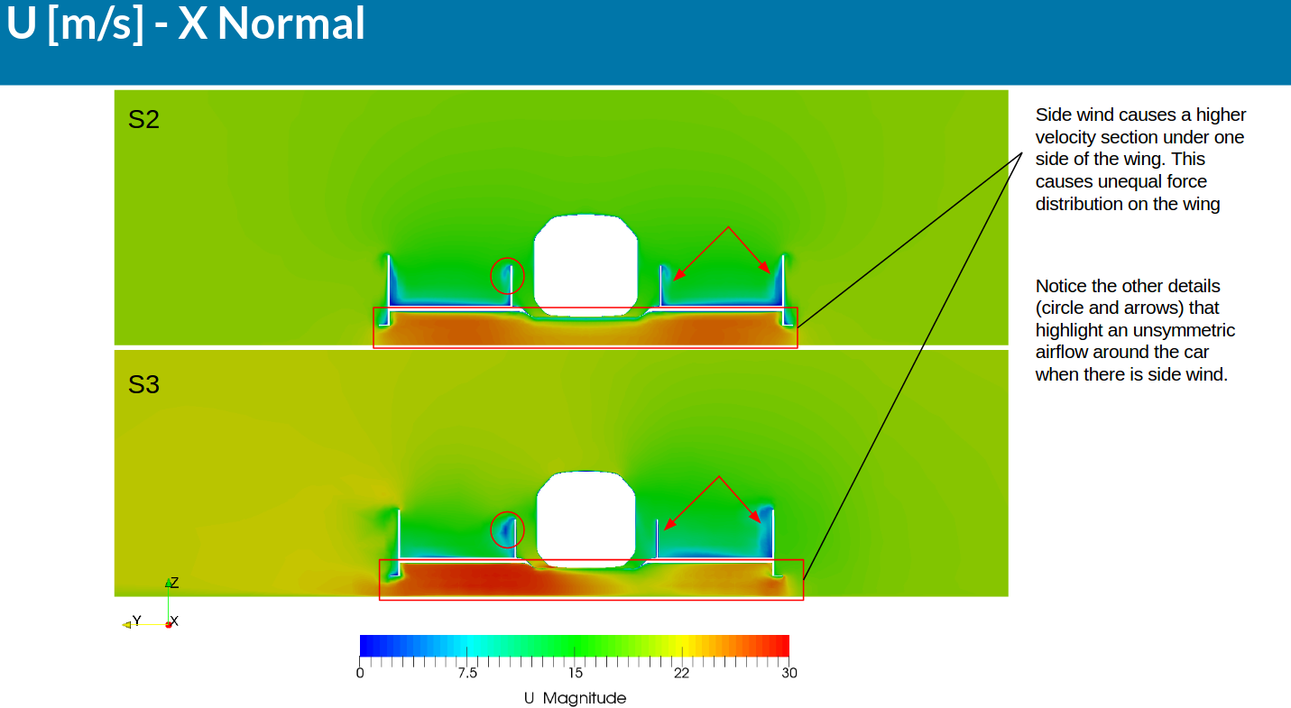
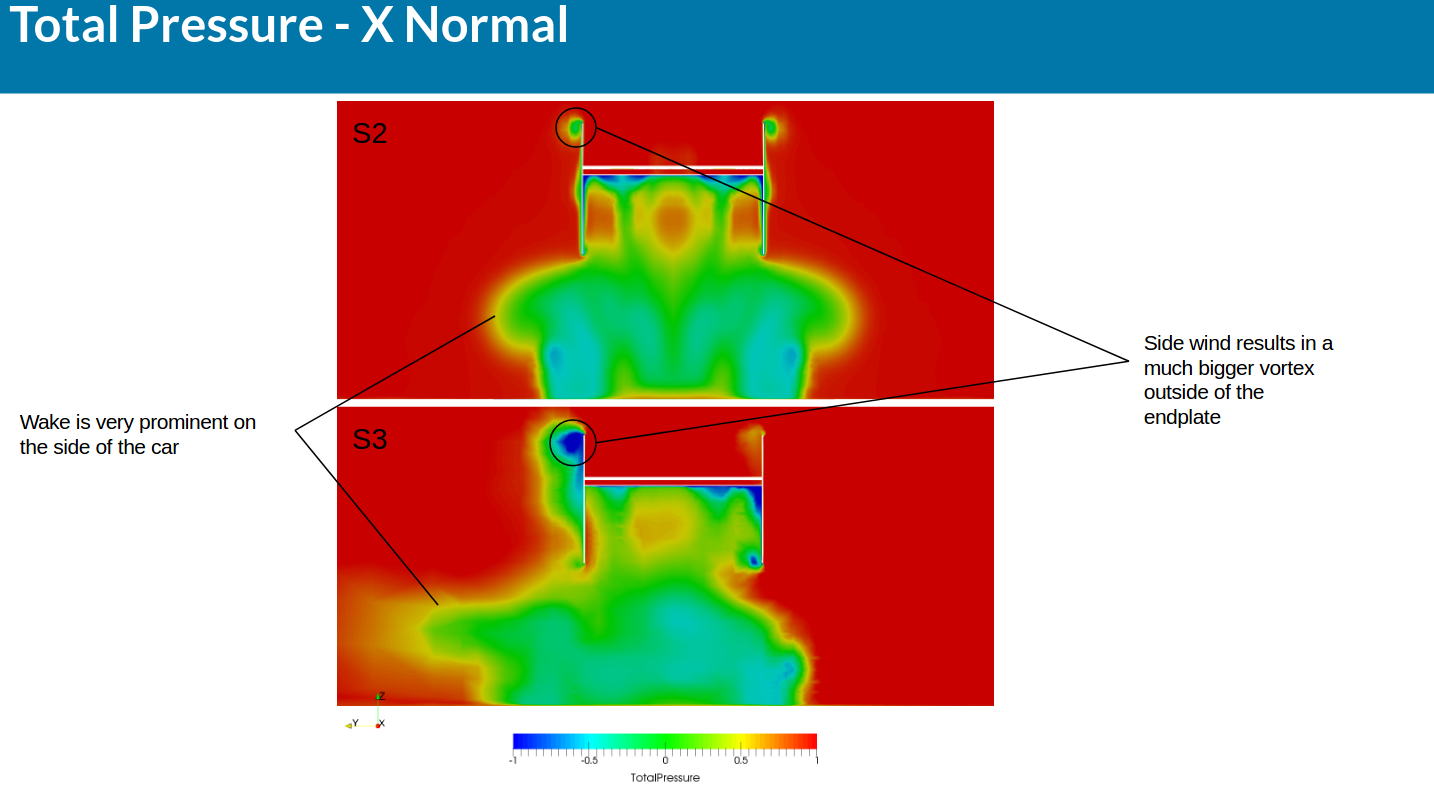
Welcome to the second part of the step-by-step tutorial for the simulation of a Formula SAE full car with side wind. In this part of the tutorial we will show you the final steps for the simulation setup and we will go over the post processing of the results. Like last session, we will also go through some of the results and what they mean.
Simulation Setup (Part 2)
Numerics
After defining all the boundary conditions, we will proceed to set up the numerics for our simulation.
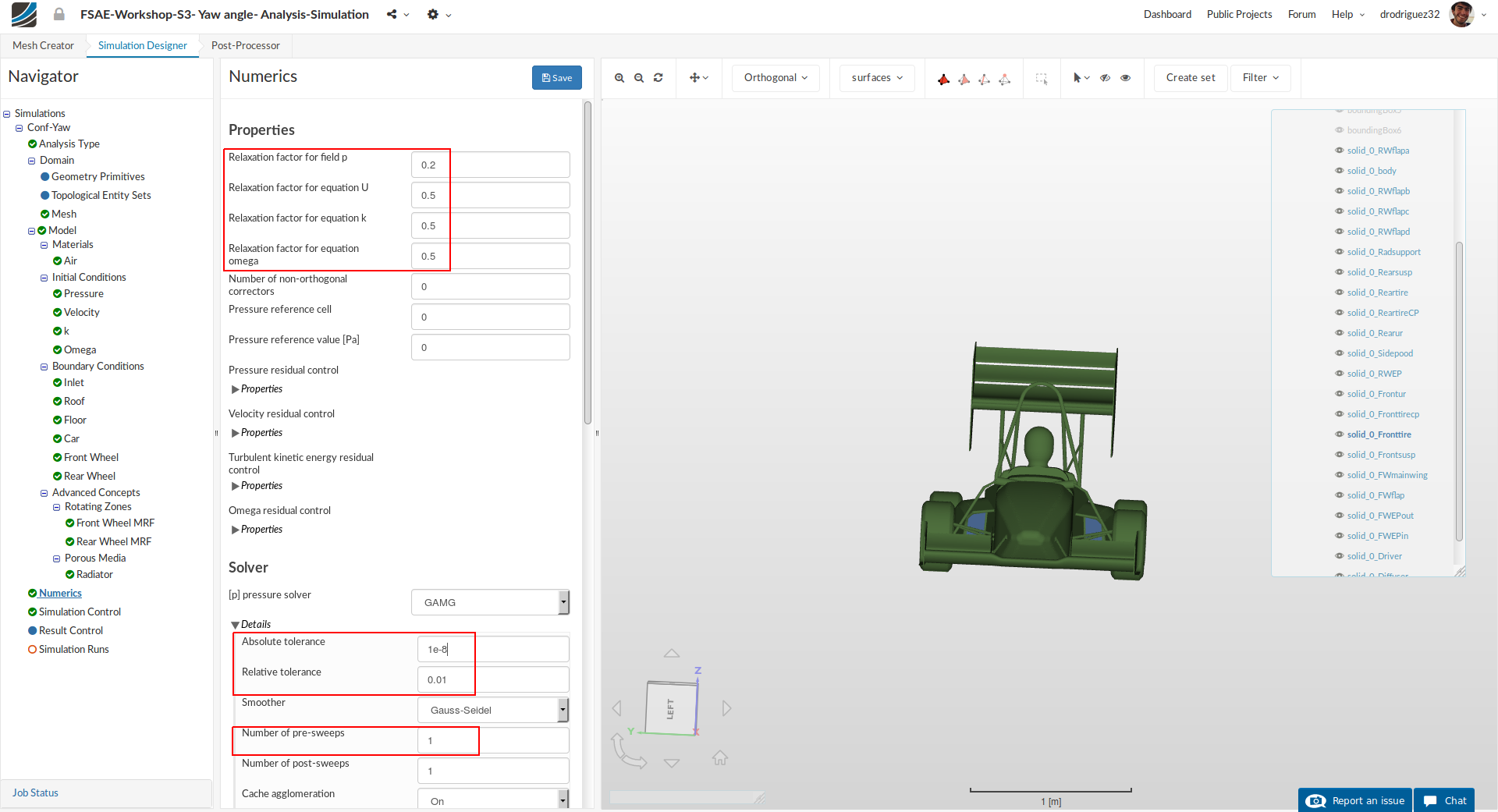
Go to Numerics and change:
-
Relaxation factor for field p, Relaxation factor for equation U, Relaxation factor for equation k and Relaxation factor for equation omega to 0.2, 0.5, 0.5 and 0.5 respectively.
-
Furthermore, under [p] pressure solver, change Absolute tolerance, Relative tolerance and Number of pre-sweeps to 1e-8, 0.01 and 1 respectively.
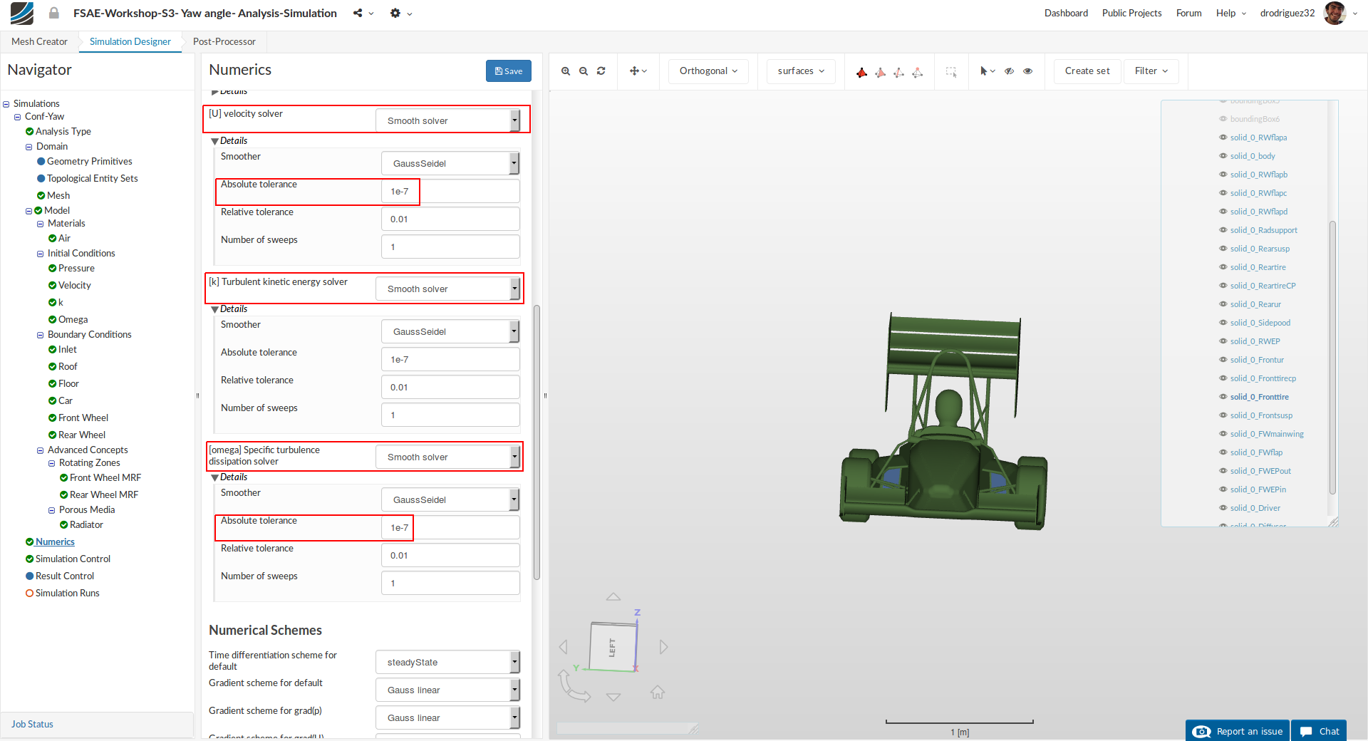
Scroll down until [U] velocity solver and change:
- [U] velocity solver to Smooth solver, Smoother to symGaussSeidel and Absolute tolerance to 1e-7. Do the same for [k] Turbulent kinetic energy solver and [omega] Specific turbulence dissipation solver
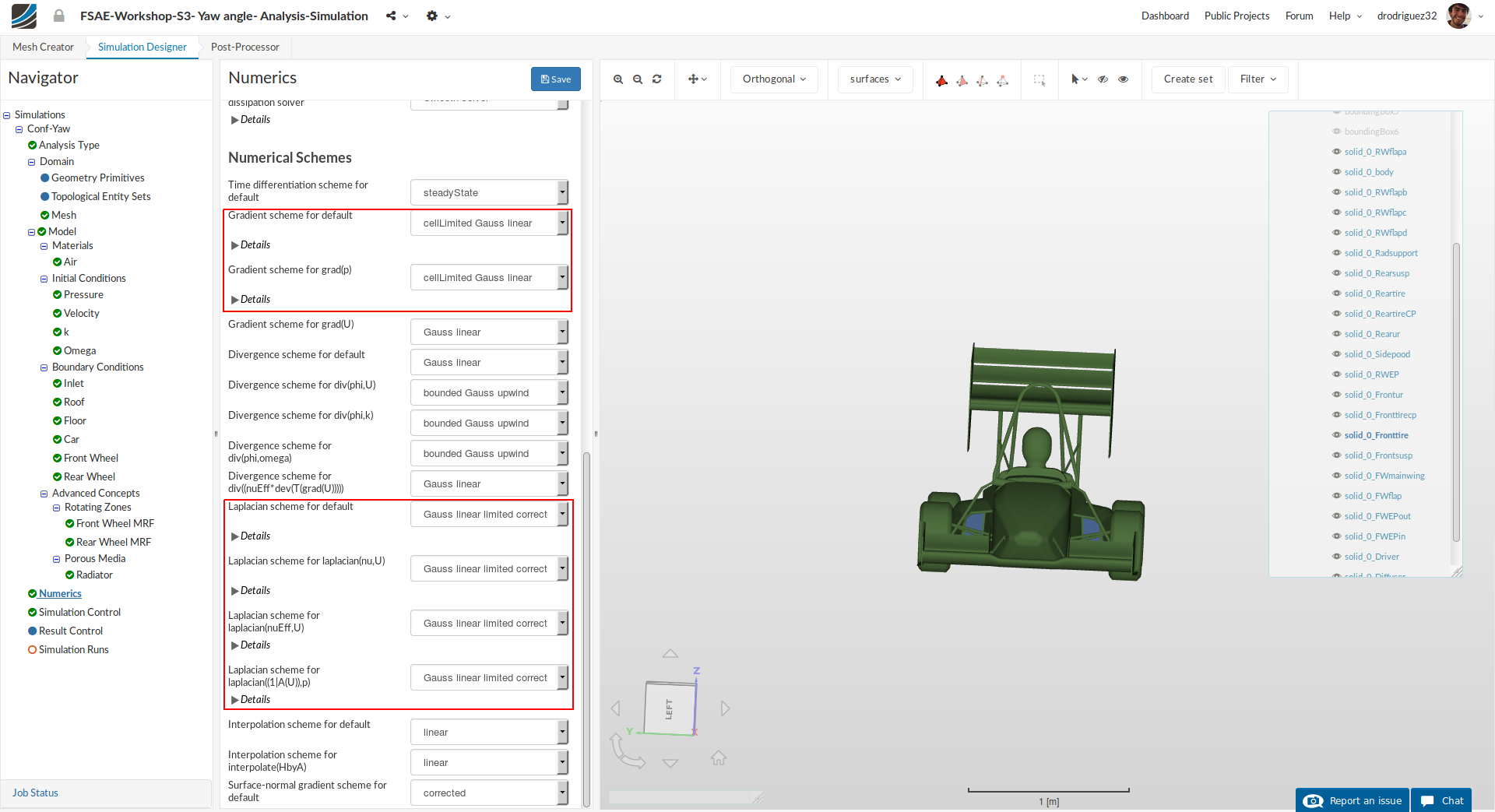
Scroll down to the end and change:
-
BothGradient scheme for default and Gradient scheme for grad(p) to cellLimited Gauss linear
-
Laplacian scheme for default, Laplacian scheme for laplacian(nu,U), Laplacian scheme for laplacian(nuEff,U) and Laplacian scheme for laplacian((1|A(U)),p) to Gauss linear limited corrected
-
Click Save to register all of your changes.
Simulation Control
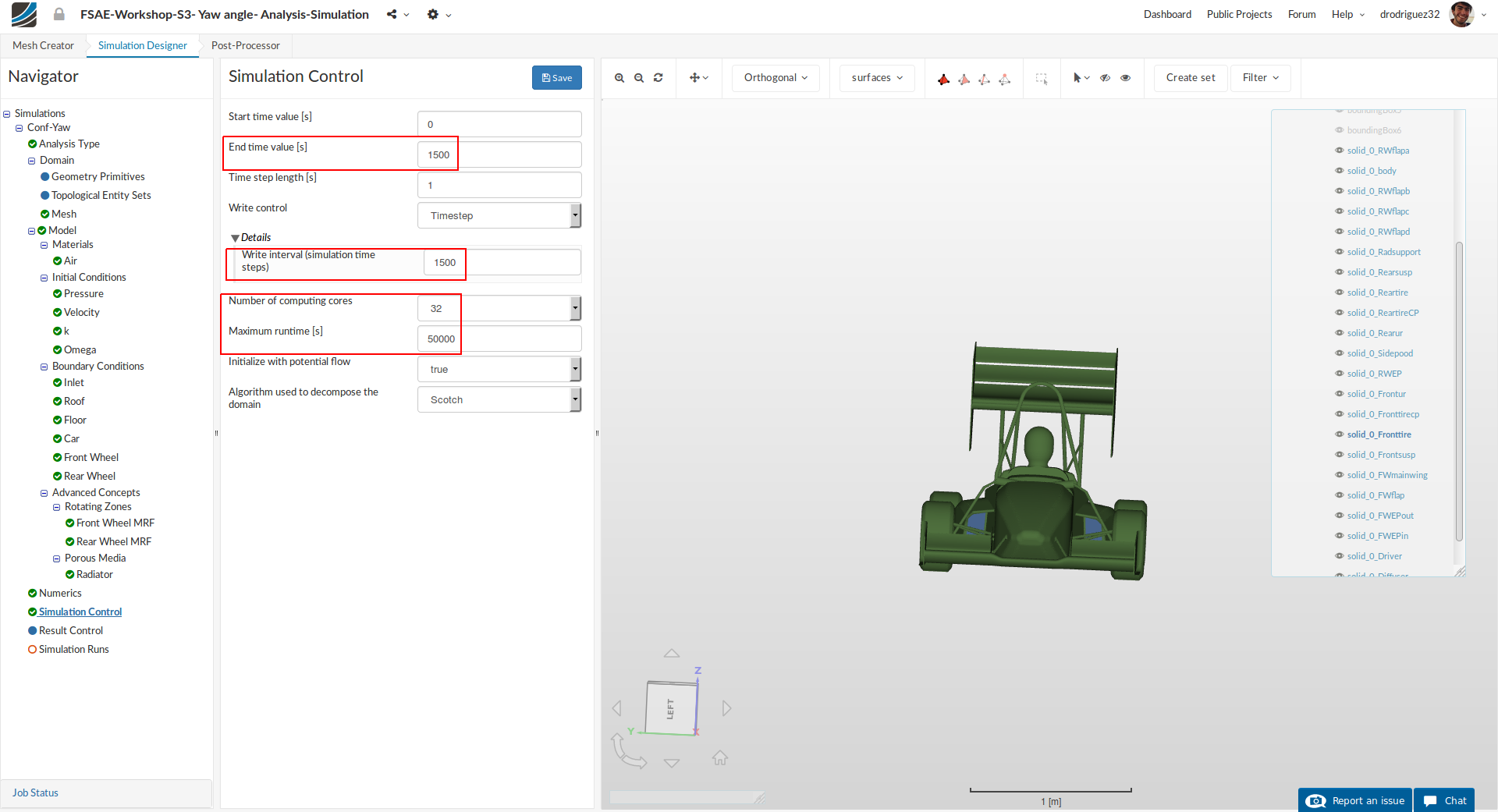
For the simulation control we will specify the End time value [s], Number of computing cores and Maximum runtime [s] to 1500, 32 and 50,000 respectively. Also, under Write Control > Details change the value to 1500.
Result Control
As the last step before starting our simulation run, we will create result control items in order to obtain graphical data of the results.
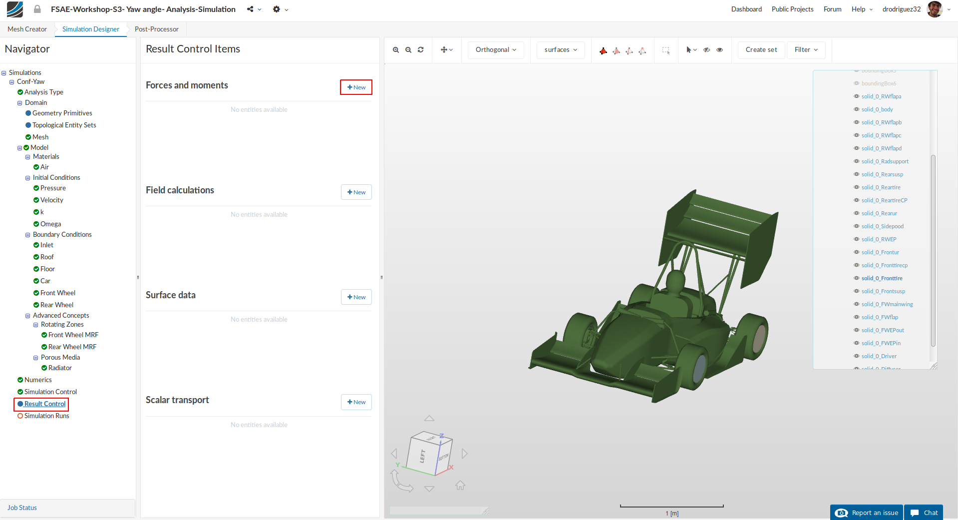
Go to Result Control and click +New next to Forces and Moments.
1. Front Wing
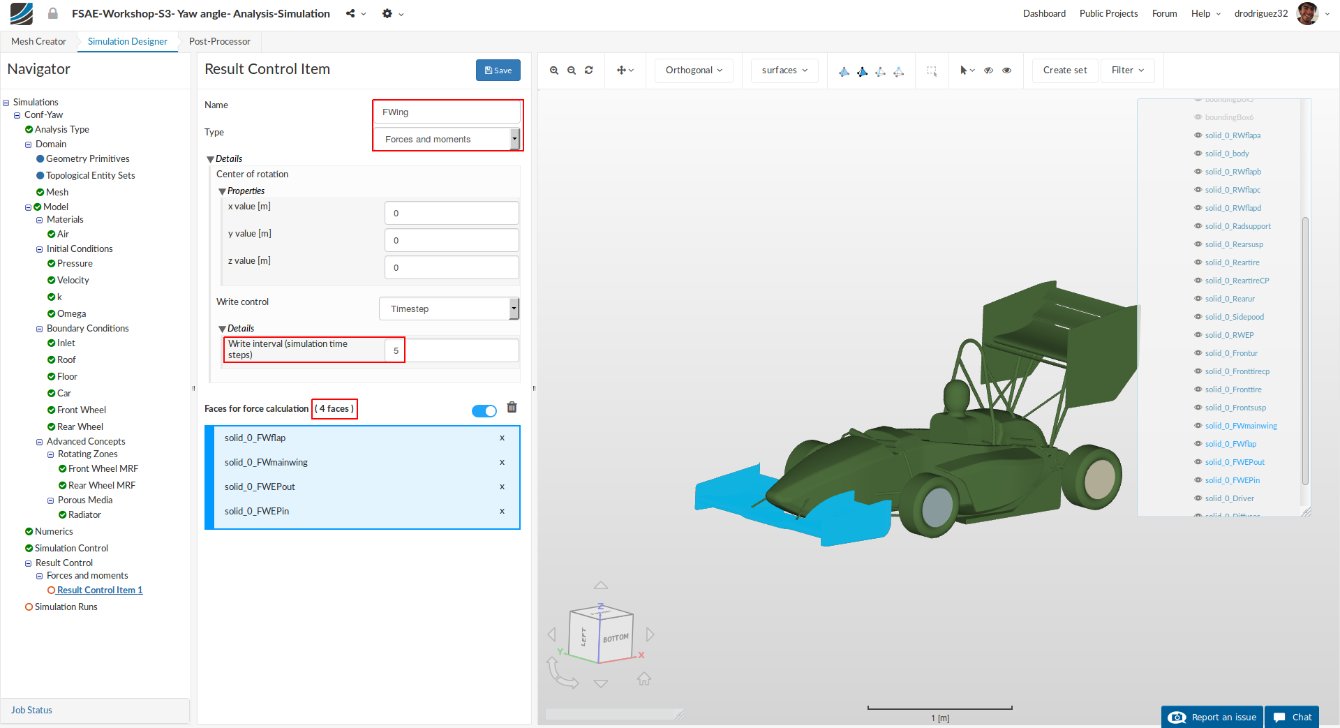
A new Force and Moment result control item will be created. Rename it to FWing (optional).
Change the Write interval (simulation time steps) to 5
Select solid_0_FWmainwing, solid_0_FWEPin, solid_0_FWEPout and solid_0_FWflap, you should see them under Faces for force calculation.
Click Save to register your changes.
2. Rear Wing
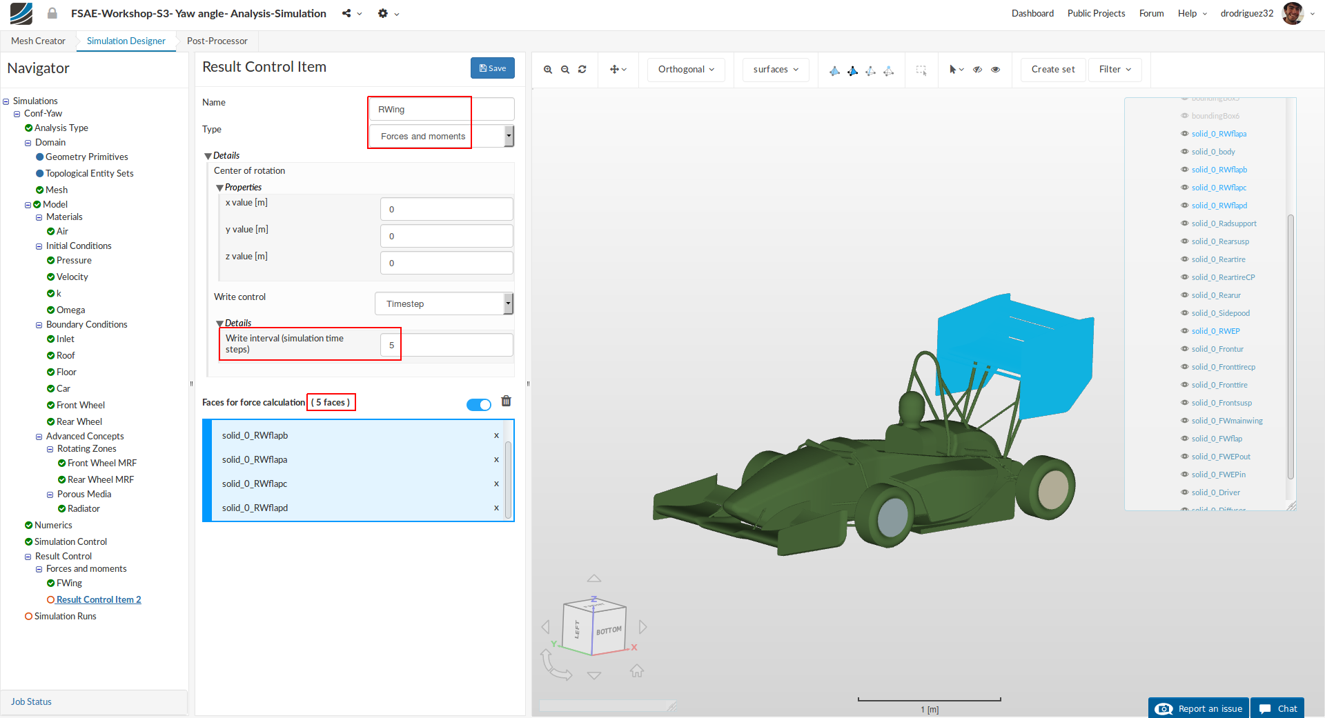
Create a new Force and Moment result control item for the rear wing. Rename it to RWing (optional).
Change the Write interval (simulation time steps) to 5
Select solid_0_RWEP, solid_0_RWflapa, solid_0_RWflapb, solid_0_RWflapc and solid_0_RWflapd, you should see them under Faces for force calculation.
Click Save to register your changes.
3. Diffuser
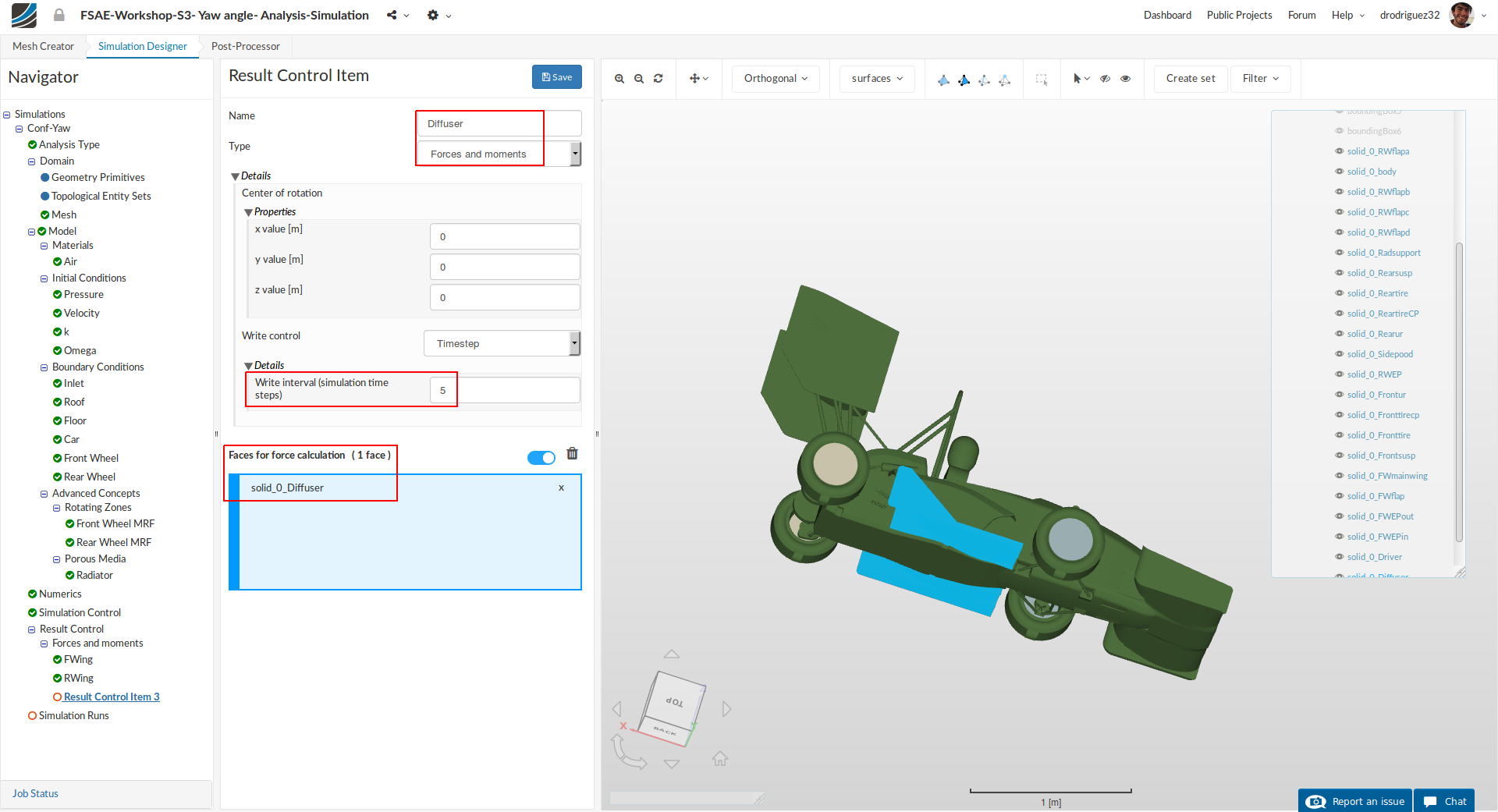
Create a new Force and Moment result control item for the diffuser. Rename it to Diffuser (optional).
Change the Write interval (simulation time steps) to 5
Select solid_0_Diffuser, you should see it under Faces for force calculation.
Click Save to register your changes.
4. Front Wheel
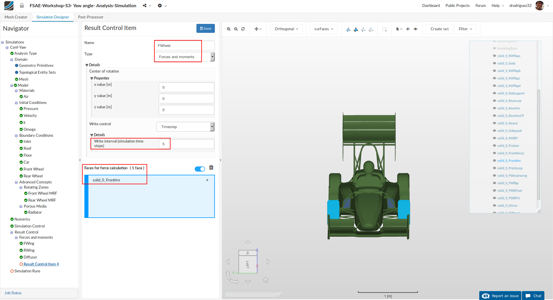
Create a new Force and Moment result control item named FWheel (optional).
Change the Write interval (simulation time steps) to 5
Select solid_0_Fronttire, you should see it under Faces for force calculation.
Click Save to register your changes.
5. Rear Wheel
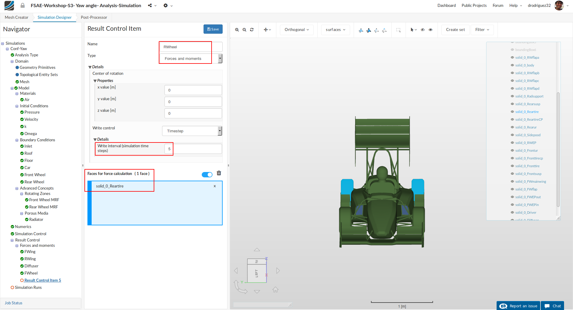
Create a new Force and Moment result control item named RWheel (optional).
Change the Write interval (simulation time steps) to 5
Select solid_0_Reartire, you should see it under Faces for force calculation.
Click Save to register your changes.
6. Body
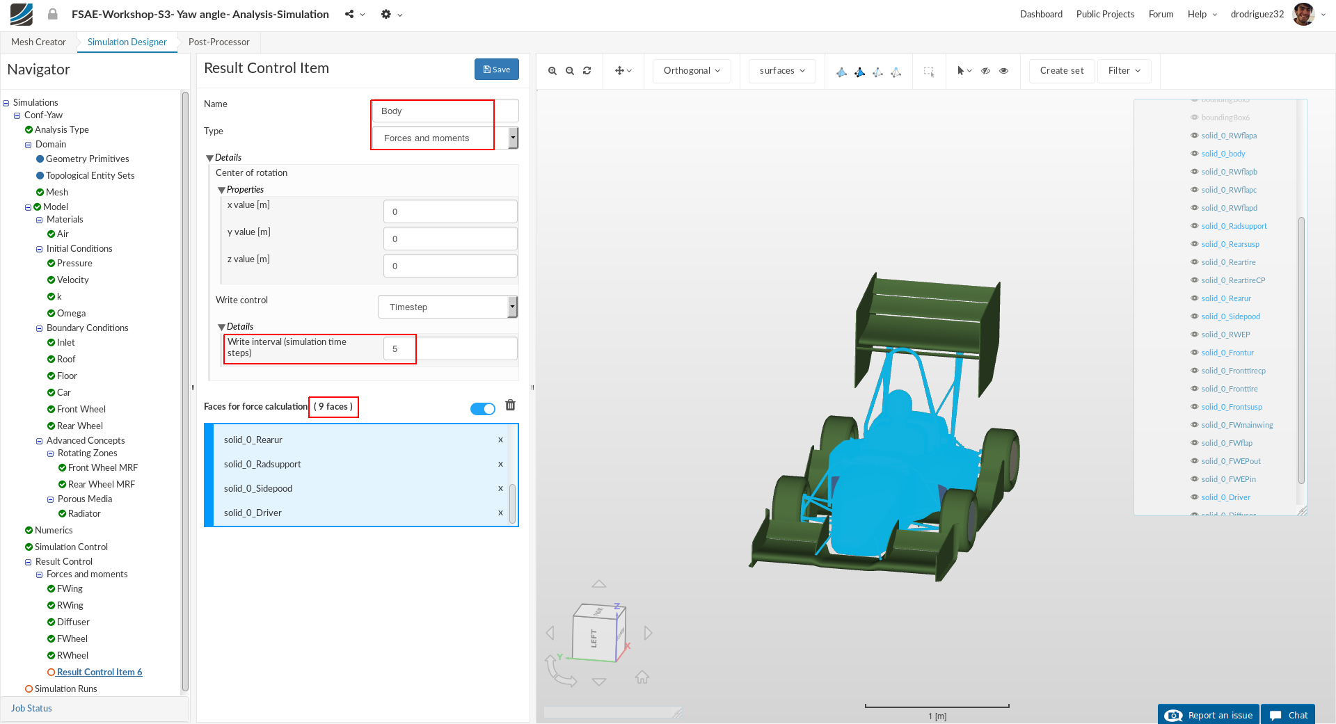
Create a new Force and Moment result control item named Body (optional).
Change the Write interval (simulation time steps) to 5
Select solid_0_body, solid_0_Frontsusp, solid_0_Rearsusp, solid_0_Barre, solid_0_Sidepood, solid_0_Frontur, solid_0_Radsupport, solid_0_Rearur and solid_0_Driver. You should see them under Faces for force calculation.
Click Save to register your changes.
Simulation Run
Once all the above steps are defined, we will proceed to create our first simulation run.
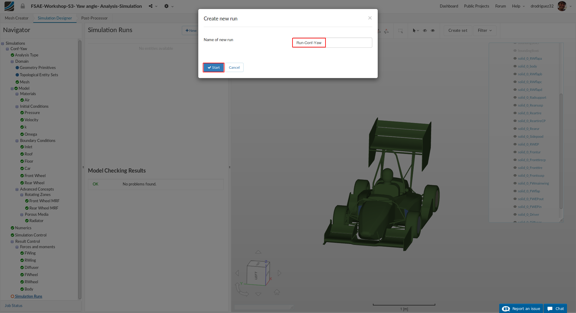
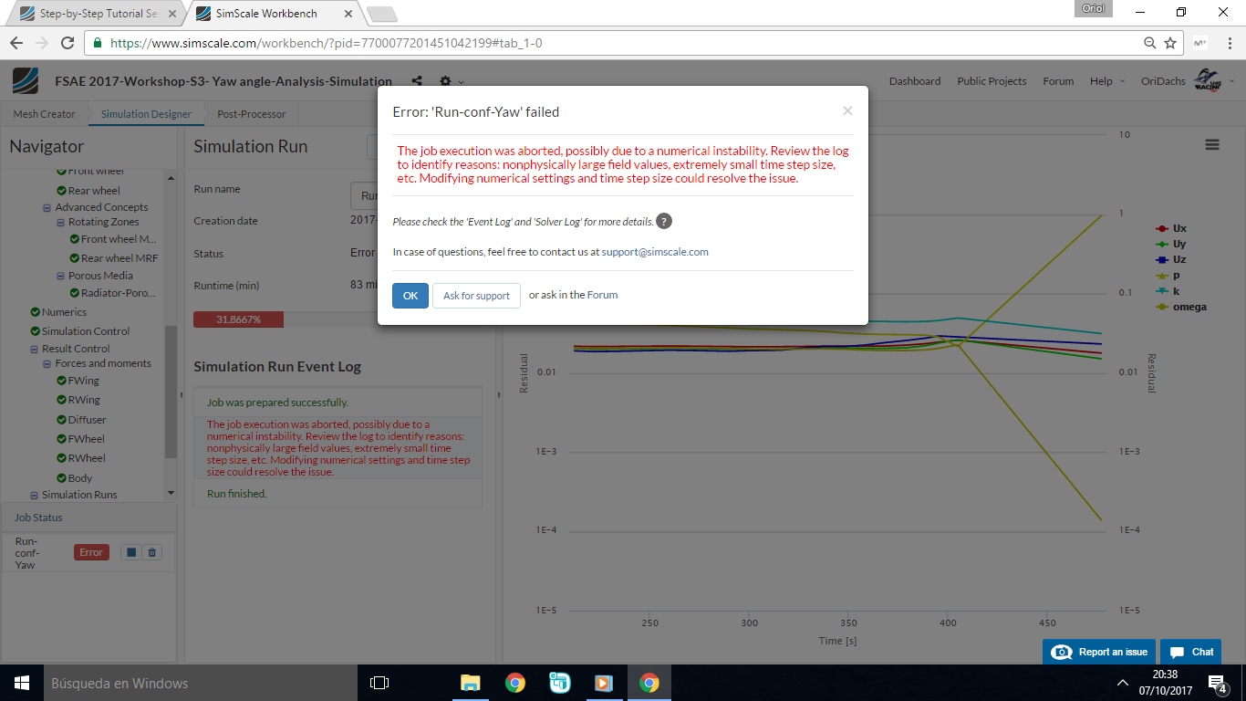
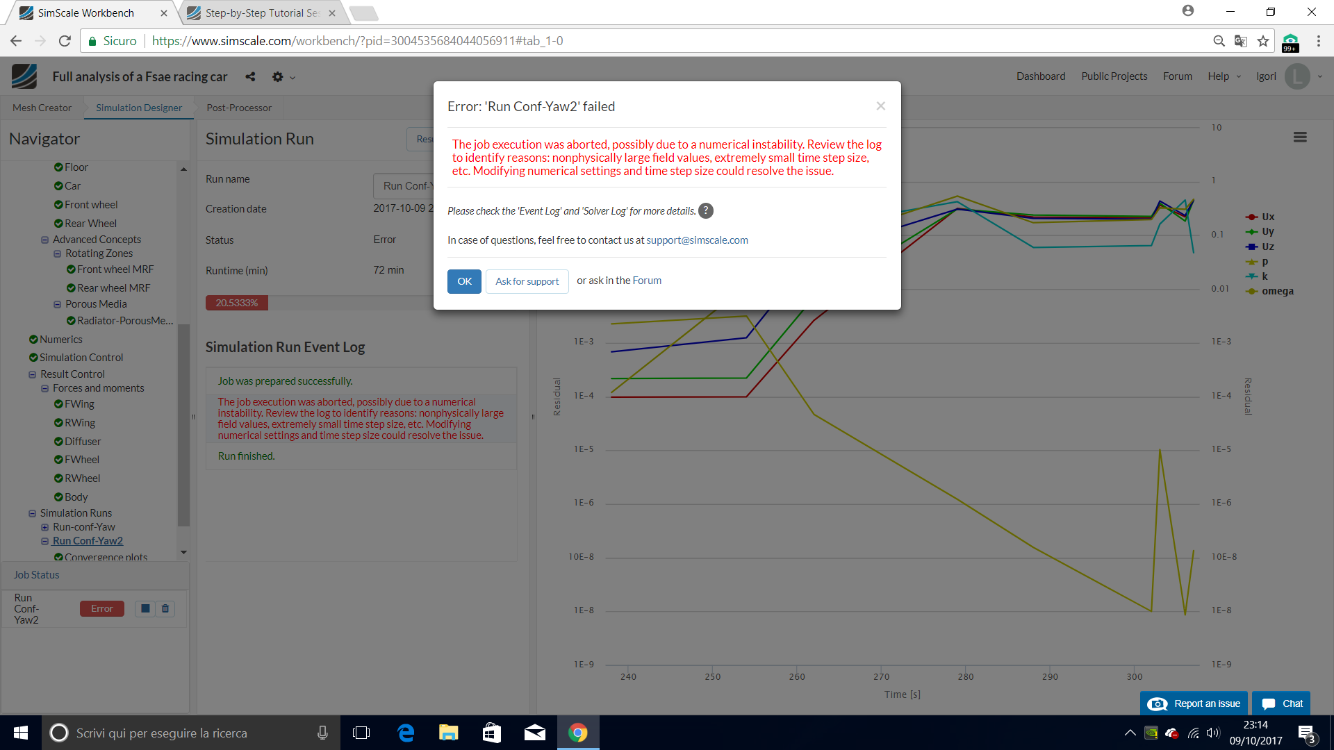
Go to Simulation Runs and click on +New. A window will pop up, give a reasonable name to the run e.g. Run-conf-Yaw in this case (optional) and click Create in order to create a new run.
After the run is created, click Start to start the created run. The simulation run can take up to ~190 minutes (~3 hrs.)
Post-Processing
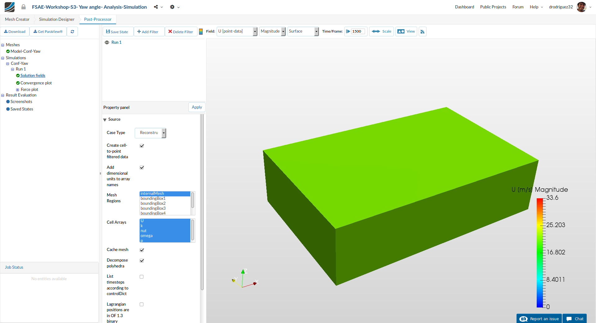
Once in Post-Processor, click on Solution fields under Run-Conf-Yaw in order to load the results in viewer. Due to full car model that we are using, it can take up to 20 minutes to load the results in to the viewer.
In order to reduce the time of loading the results we suggest for you to select only U and P under the Property panel and Cell Arrays.
For further instructions about how to post-process your results please follow the same steps detailed in the exercise in Part 2 of Session 2.
Step-by-Step Tutorial Session 2 - Full Car Aerodynamics (Part 2)
Homework Submission
For your homework, your task is to investigate the full car running in a straight line at 20 m/s with side wind. You will have the same model we used for the last session, so you will setup porous media, MRF (rotating) zones, rotating walls, and the flap angle will be 0 degrees. Think about how this setup differs from the previous one and think about the impact of the side wind on the performance of the car and the flow behavior around it.
The step-by-step tutorial below contains all of the steps for setting up the simulation in SimScale and visualizing the results.
We’ve made an update to the platform and the sharing procedure has changed. Please go to the following link to see how to get a sharing link for your project:
New Sharing on SimScale
Homework Deadline: October 17th, 11:59 pm CEST