Recording

Homework Submission
For your homework, your task is to investigate the full car running in a straight line at 20 m/s with side wind. You will have the same model we used for the last session, so you will setup porous media, MRF (rotating) zones, rotating walls, and the flap angle will be 0 degrees. Think about how this setup differs from the previous one and think about the impact of the side wind on the performance of the car and the flow behavior around it.
The step-by-step tutorial below contains all of the steps for setting up the simulation in SimScale and visualizing the results.
We’ve made an update to the platform and the sharing procedure has changed. Please go to the following link to see how to get a sharing link for your project:
New Sharing on SimScale
Homework Deadline: October 17th, 11:59 pm CEST
Click Here to Submit your Homework
Outline
Part 1:
-
Introduction
-
Project Import
-
Mesh Generation
a. Geometry Primitives
b. Mesh Refinements
c. Start Operation -
Simulation Setup (Part 1)
a. Analysis Type
b. Domain
c. Material
d. Initial Conditions
e. Boundary Conditions
Part 2:
-
Simulation Setup (Part 2)
a. Numerics
b. Simulation Control
c. Result Control
d. Simulation Runs -
Post Processing on SimScale
-
Result Analysis
a. Highlights
b. Yaw Angle Comparison
Introduction
In this exercise we will investigate the effects of side wind on the performance of the car. Your task is to investigate the full car model Model-Conf-Yaw. The velocity of the car will be considered constant at 20 m/s with side wind.
Project Import
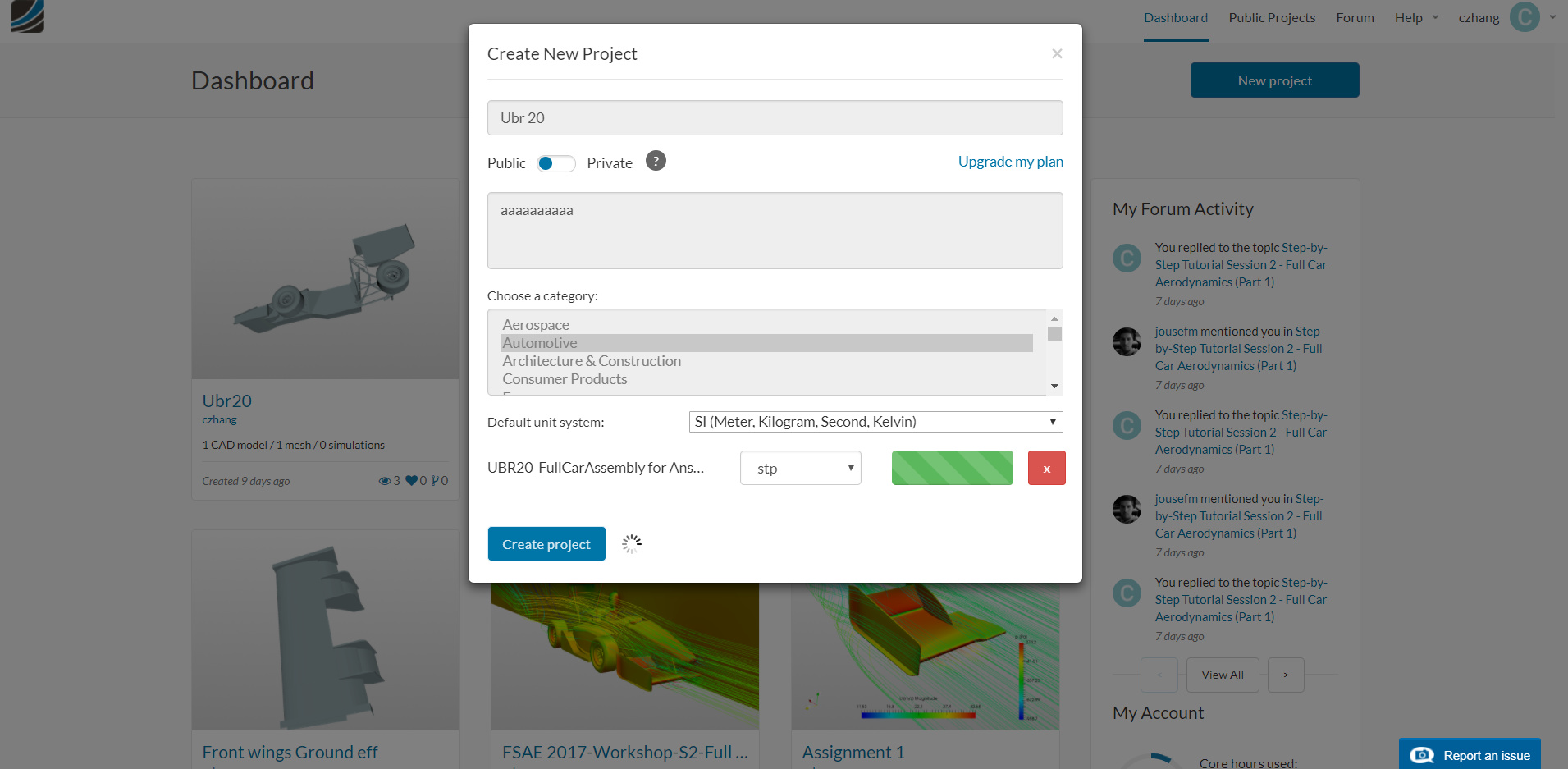
To start this exercise, please import the project into your workspace by clicking on the link below:
If the project appears to be private, please make a copy of it to work on it.
Mesh Generation
In the Mesh Creator tab, click on the geometry Model-Conf-Yaw
Click on the New Mesh button
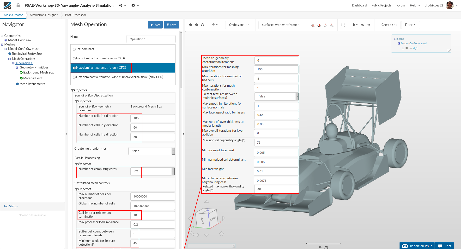
A new mesh operation will be generated automatically. Next change (some of the settings have been set as default by SimScale. Please double check all your settings):
-
Type to Hex-dominant parametric (only CFD)
-
Bounding Box geometry primitive to the following:
Number of cells in x direction to 105
Number of cells in y direction to 60
Number of cells in z direction to 30 -
Number of parallel computing cores to 32
[Scroll down to change other values to optimize the meshing parameters]
[You can also ctrl+f to find each setting]
-
Cell limit for refinement termination to 10
-
Buffer cell count between refinement levels and Minimum angle for feature detection [°] to 1 and 45 respectively
-
Mesh-to-geometry conformation iterations to 6
-
Max iterations for meshing algorithm to 150
-
Max iterations for removal of bad cells to 8
-
Max iterations for mesh conformation to 1
-
Detect features between multiple surfaces to false
-
Max smoothing iterations for surface normals [-] to 1
-
Max face aspect ratio for layers [-] and Max ratio of layer thickness to medial length [-] to 0.55 and 0.35 respectively
-
Max overall iterations for layer addition to 3
-
Max non-orthogonality angle to 75
-
Min cosine for face twist, Min normalized cell determinant,Min face weight and Min volume ratio between neighbouring cells to 0.005, 0.005, 0.01 and 0.0075 respectively
-
Relaxed max non-orthogonality angle to 80
-
Click Save to register changes.
Geometry Primitives
Next we’re going to define geometry primitives like in the past sessions so that we can get refinement regions.
Background Mesh Box
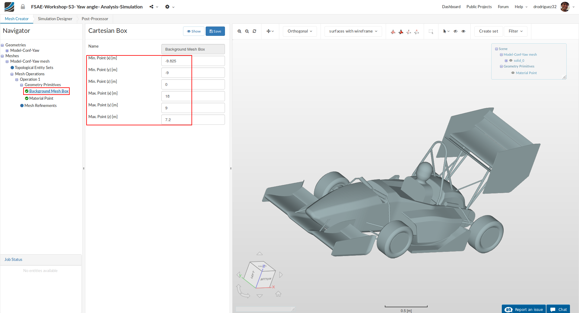
Go to the Background Mesh Box item and change the mesh box dimensions to the values shown below.
- Min. Point (x) [m]: -9.825
- Min. Point (y) [m]: -9
- Min. Point (z) [m]: 0
- Max. Point (x) [m]: 18
- Max. Point (y) [m]: 9
- Max. Point (z) [m]: 7.2
Click Save to save the changes.
Material Point

Go to the MaterialPoint item and change the values to:
- Center (x) [m]: 0
- Center (y) [m]: 0
- Center (z) [m]: 3
Click Save to save the changes.
Cartesian Box-lower
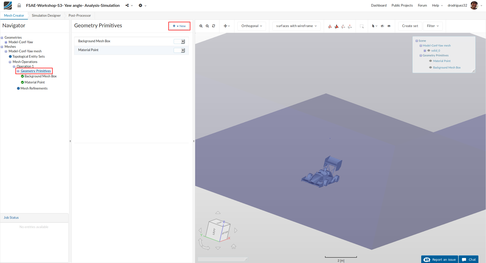
Next go back to Geometry Primitives and click on +New and then Cartesian Box to define a new Cartesian box that will be used to define mesh refinement area.
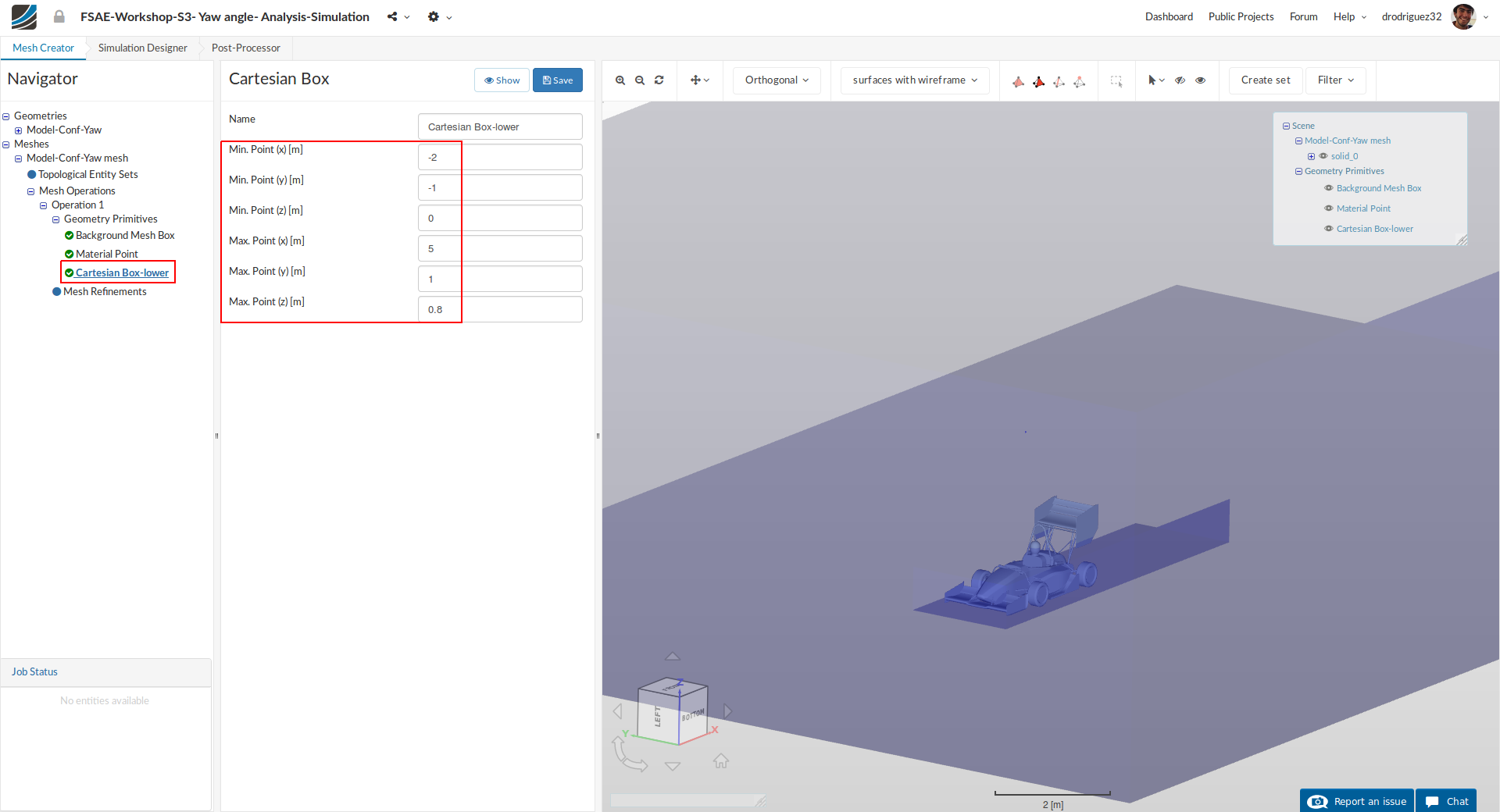
After creating a new Cartesian box, you will be directed to the definition of this Cartesian box. Rename it to Cartesian Box-lower (optional) and change the dimensions to:
- Min. Point (x) [m]: -2
- Min. Point (y) [m]: -1
- Min. Point (z) [m]: 0
- Max. Point (x) [m]: 5
- Max. Point (y) [m]: 1
- Max. Point (z) [m]: 0.8
Click Save to register your changes.
Cartesian Box-upper
Follow the same procedure to create a second cartesian box geometry primitive.
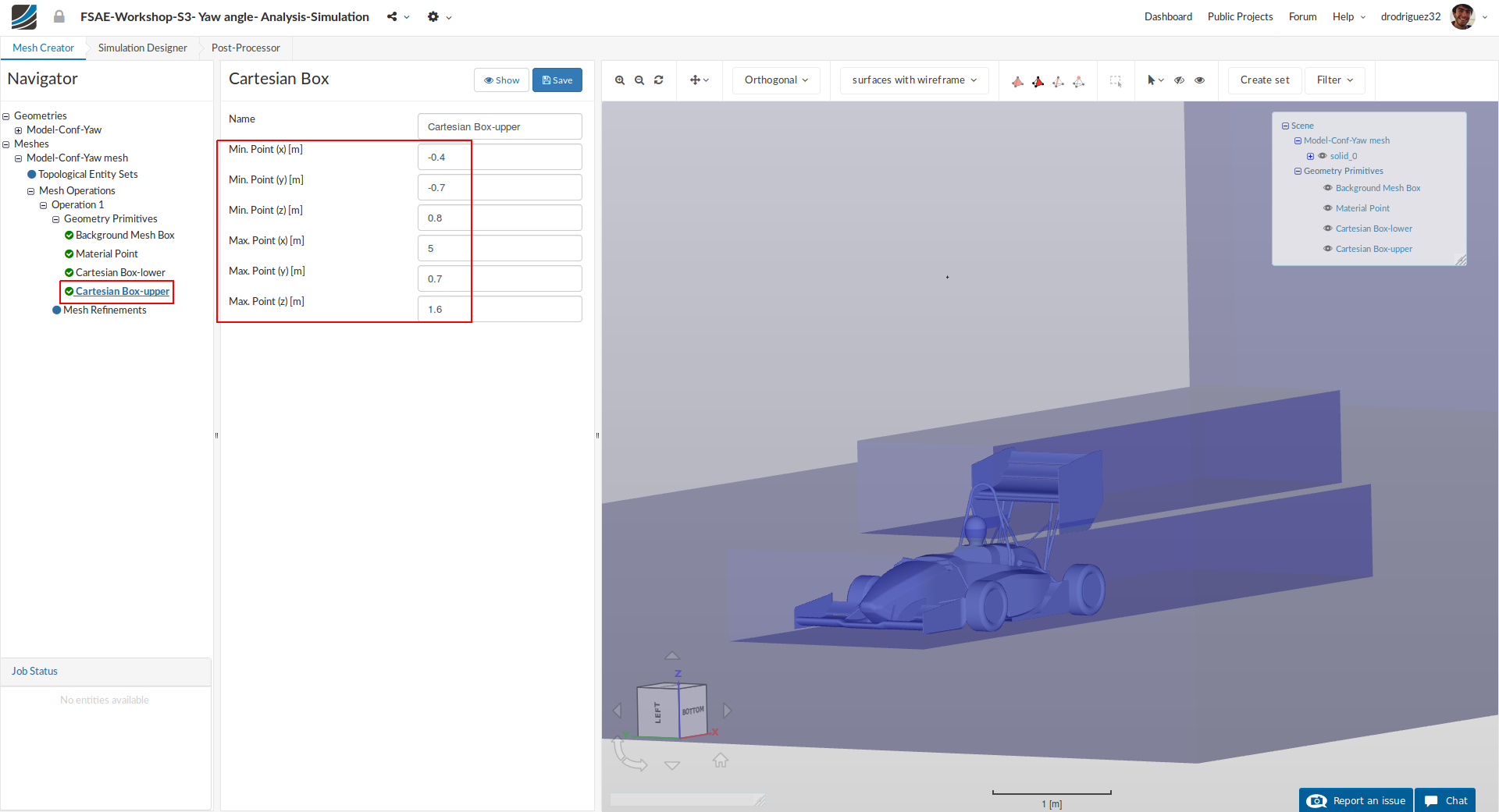
Rename it to Cartesian Box-upper (optional). This time change the dimensions to:
- Min. Point (x) [m]: -0.4
- Min. Point (y) [m]: -0.7
- Min. Point (z) [m]: 0.8
- Max. Point (x) [m]: 5
- Max. Point (y) [m]: 0.7
- Max. Point (z) [m]: 1.6
Click Save to register your changes.
Mesh Refinements
Now we will start creating the mesh refinements. For this proceed to Mesh Refinements and click +New
Mesh Refinement 1 - Surface
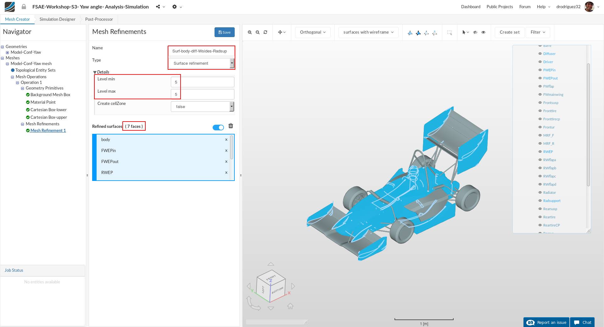
A new mesh refinement will be created. Rename it to Surf-body-diff-Wsides-Radsup (optional).
Change the Type to Surface refinement
Set Level min and Level max to 5 and 5 respectively.
From the navigator on the right (or directly in the viewer) select body, FWEPin, FWEPout, RWEP, Diffuser, Radsupport and Driver. You should see these 7 faces in the blue highlighted area under Refined Surfaces.
Click Save to register your changes.
Mesh Refinement 2 - Surface
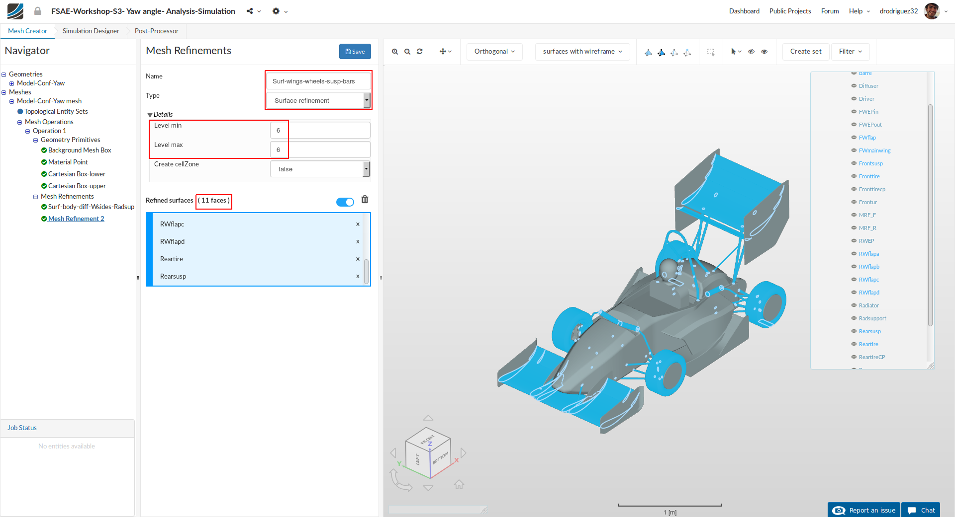
Follow the same procedure and create a new mesh refinement named Surf-wings-wheels-susp-bars (optional).
Change the Type to Surface refinement
Set Level min and Level max to 6 and 6 respectively.
From the navigator on the right (or directly in the viewer) select FWmainwing, FWflap, RWflapa, RWflapb, RWflapc, RWflapd, Frontsusp, Rearsusp, Barre, Reartire and Fronttire. You should see these 11 faces in the blue highlighted area under Refined Surfaces.
Click Save to register your changes.
Mesh Refinement 3 - Surface
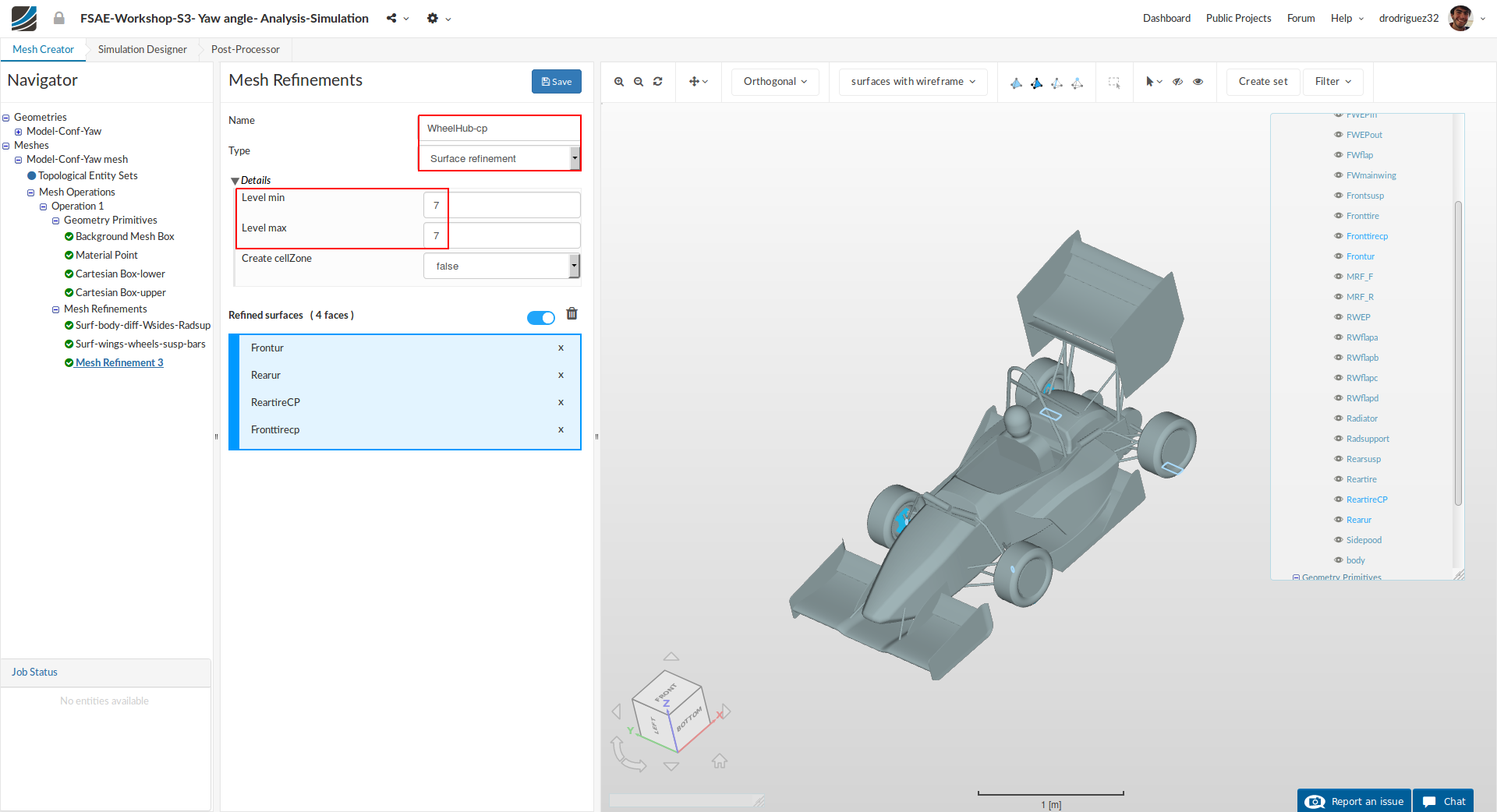
Create a new mesh refinement named WheelHub-cp (optional).
Change the Type to Surface refinement
Set Level min and Level max to 7 and 7 respectively.
From the navigator on the right (or directly in the viewer) select Frontur, Rearur, ReartireCP and Fronttirecp. You should see these 4 faces in the blue highlighted area under Refined Surfaces.
Click Save to register your changes.
Mesh Refinement 4 - Surface
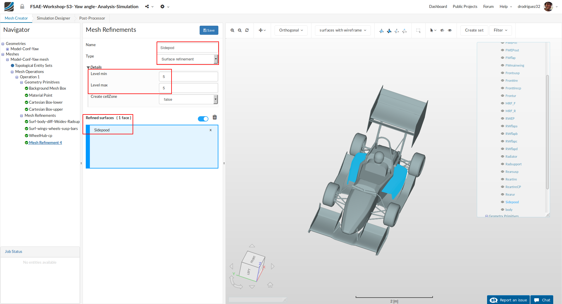
Create a new mesh refinement named Sidepod (optional).
Change the Type to Surface refinement
Set Level min and Level max to 5 and 5 respectively.
From the navigator on the right (or directly in the viewer) select Sidepod.
Click Save to register your changes.
Mesh Refinement 5 - Porous Zone
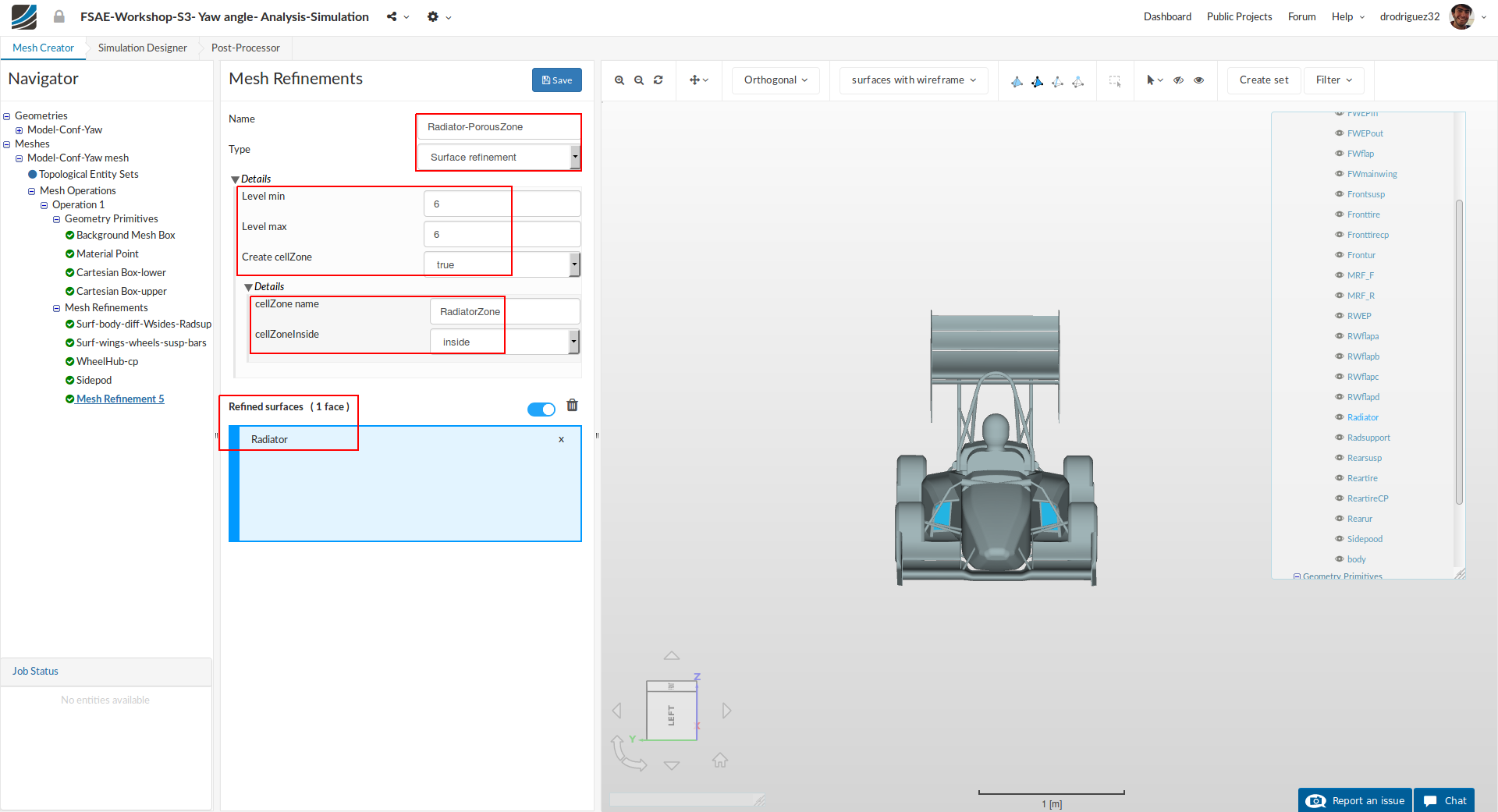
Create a new mesh refinement named Radiator-PorousZone (optional).
Change the Type to Surface refinement
Set Level min and Level max to 6 and 6 respectively.
Set Create cellZone to true and rename cellZone name to RadiatorZone.
From the navigator on the right (or directly in the viewer) select Radiator.
Click Save to register your changes.
Mesh Refinement 6 - Feature
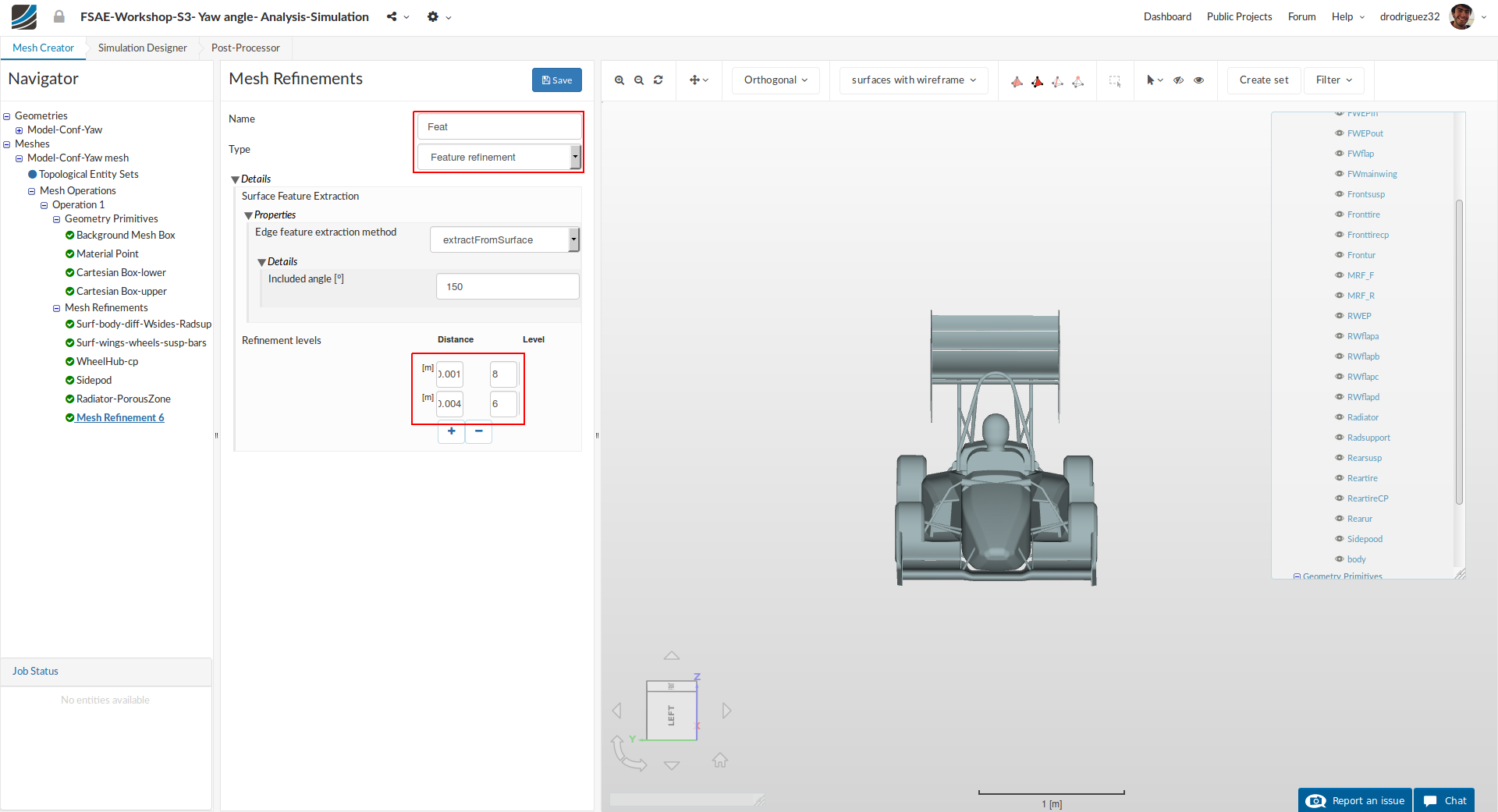
In order to create a separate feature refinement for small features, create a new mesh refinement named Feat (optional).
Change the Type to Feature refinement
Then click the + button to add an extra value. In the first row, change Distance and Level value to 0.001 and 8 respectively. Similarly, change the value to 0.004 and 6 in second row.
Click Save to register your changes.
Mesh Refinement 7 - Region
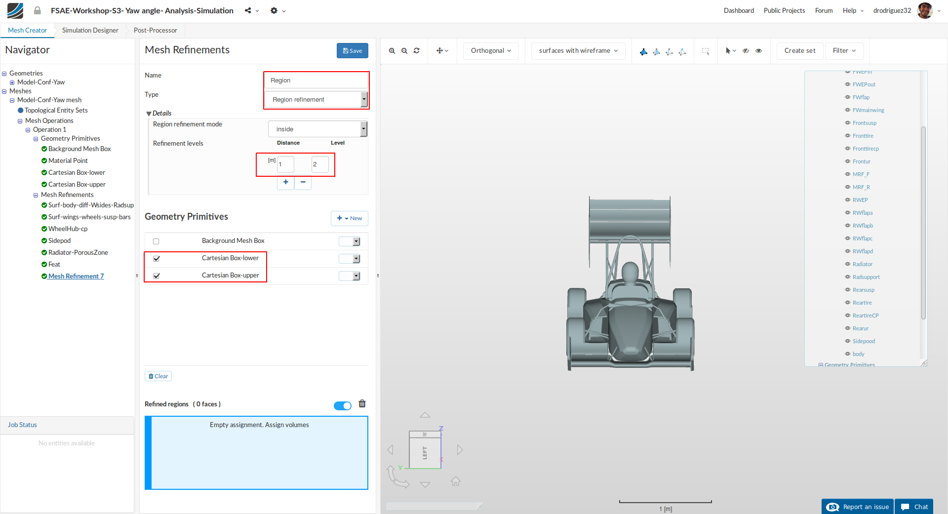
To define the refinement level for the created Cartesian box geometry primitives, create a new refinement and rename it to Region (optional).
Change the Type to Region refinement and set the level to 2
Select Cartesian Box-inner and Cartesian Box-outer under Assigned Geometry Primitives
Click Save to register the refinements for the specific cartesian boxes.
Mesh Refinement 8 - Boundary Layer
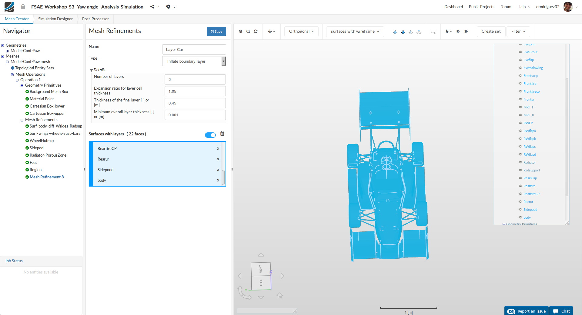
Next we will define the boundary layers over car surfaces in order to have a uniform layer refinements. Layers will allow us to accurately capture and observe the flow behavior close to the surface of the car.
Create a new refinement and rename it to Layer-Car (optional).
Change the Type to Inflate boundary layer
Then change Number of layers [-], expansionRatio [-], finalLayerThickness [-] and minThickness [-] to 3 , 1.05, 0.45 and 0.001 respectively.
Select all the faces except Radiator; Radsupport, MRF_F and MRF_R. You can do this by clicking on the box selector option in the toolbar, drawing a box over the whole car (which will select all the faces) and then unselect the faces mentioned before using the navigator on the right.
Click Save to register your changes.
Mesh Refinement 9 - Boundary Layer
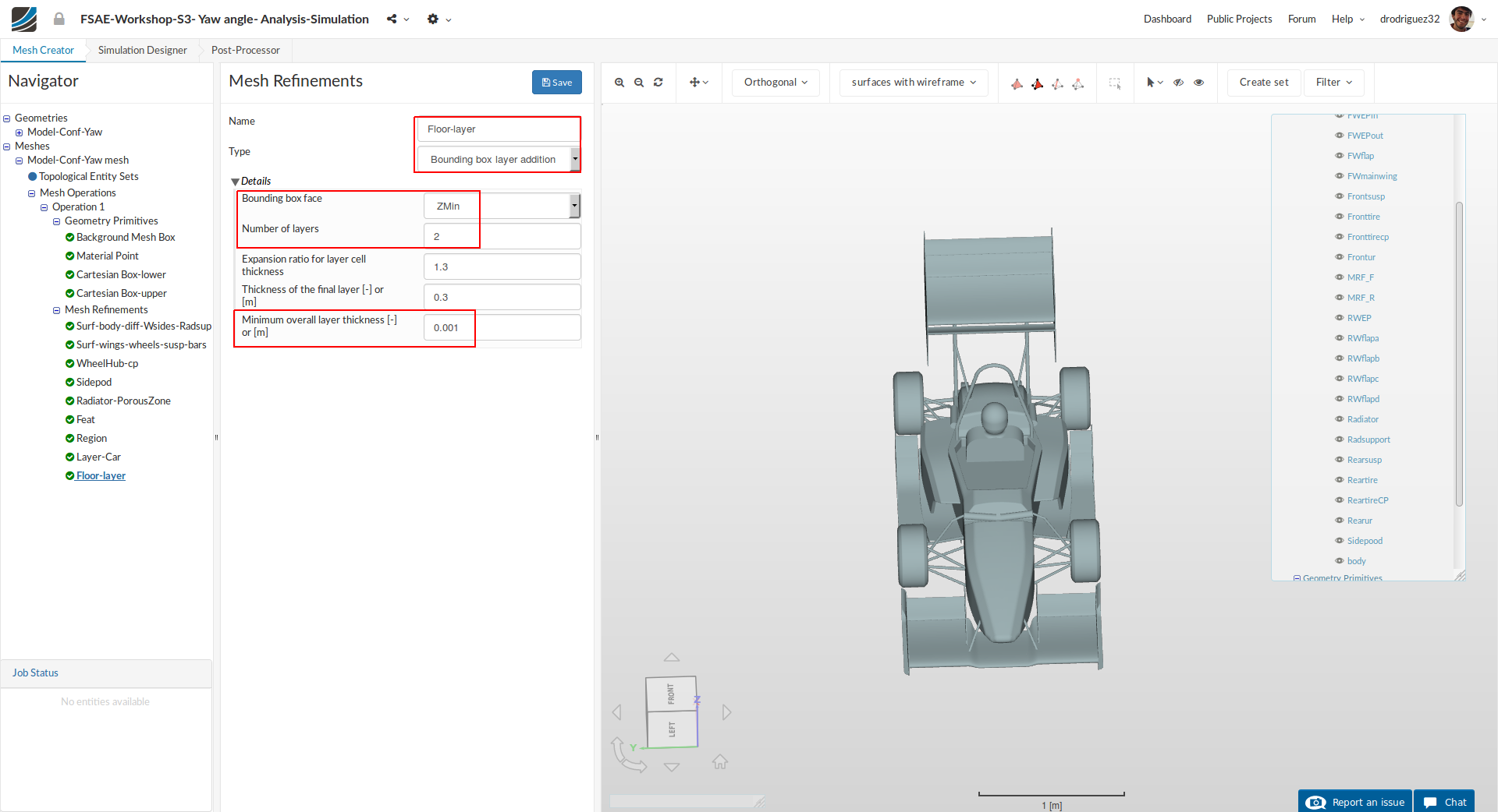
For the floor layers, create a new refinement named Floor-layer (optional).
Change the Type to Boundary box layer addition.
Change Bounding box face to Zmin and then the Number of layers and Minimum overall layer thickness [-] or [m] to 2 and 0.001 respectively.
Mesh Refinement 10 - Rotating Zone
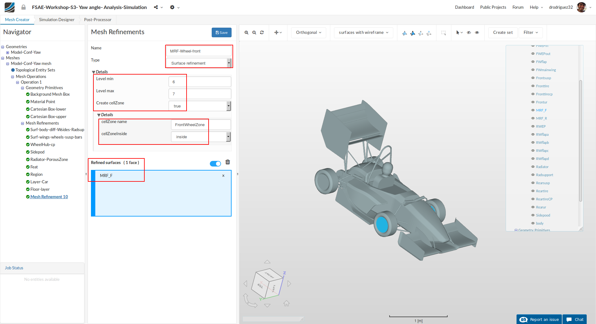
Create a new refinement for the front MRF zone named MRF-Wheel-front (optional).
Change Type to Surface refinement
Set Level min and Level max to 6 and 7 respectively.
Change Create cellZone to true and rename cellZone name to FrontWheelZone.
From the navigator on the right (or directly in the viewer) select MRF_F
Click Save to register your changes.
Mesh Refinement 11 - Rotating Zone
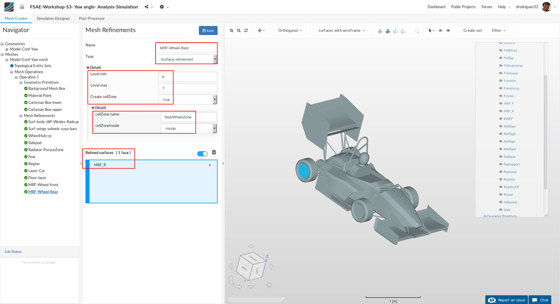
Similarly, for rear MRF zone create a new refinement named MRF-Wheel-Rear (optional).
Change the Type to Surface refinement
Set both Level min and Level max to 6 and 7 respectively.
Change Create cellZone to true and rename cellZone name to RearWheelZone.
From the navigator on the right (or directly in the viewer) select MRF_R.
Click Save to register your changes.
Start Mesh Operation

Once you have defined all 11 of the mesh refinements, go back to the Operation 1 and click Start.
Due to the fineness of the mesh, the meshing operation can take 100 to 140 minutes to finish.
Simulation
Once the meshing operation is complete, go to the Simulation Designer
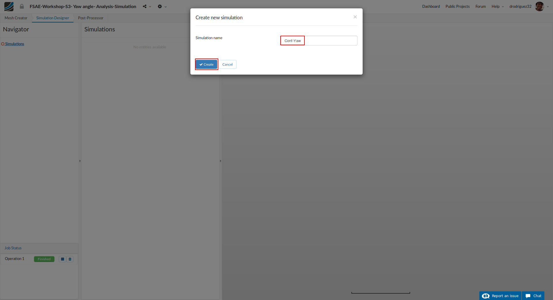
Click New Simulation and name it Conf-Yaw (optional; you can choose any name you want). Then click Create.
Analysis type
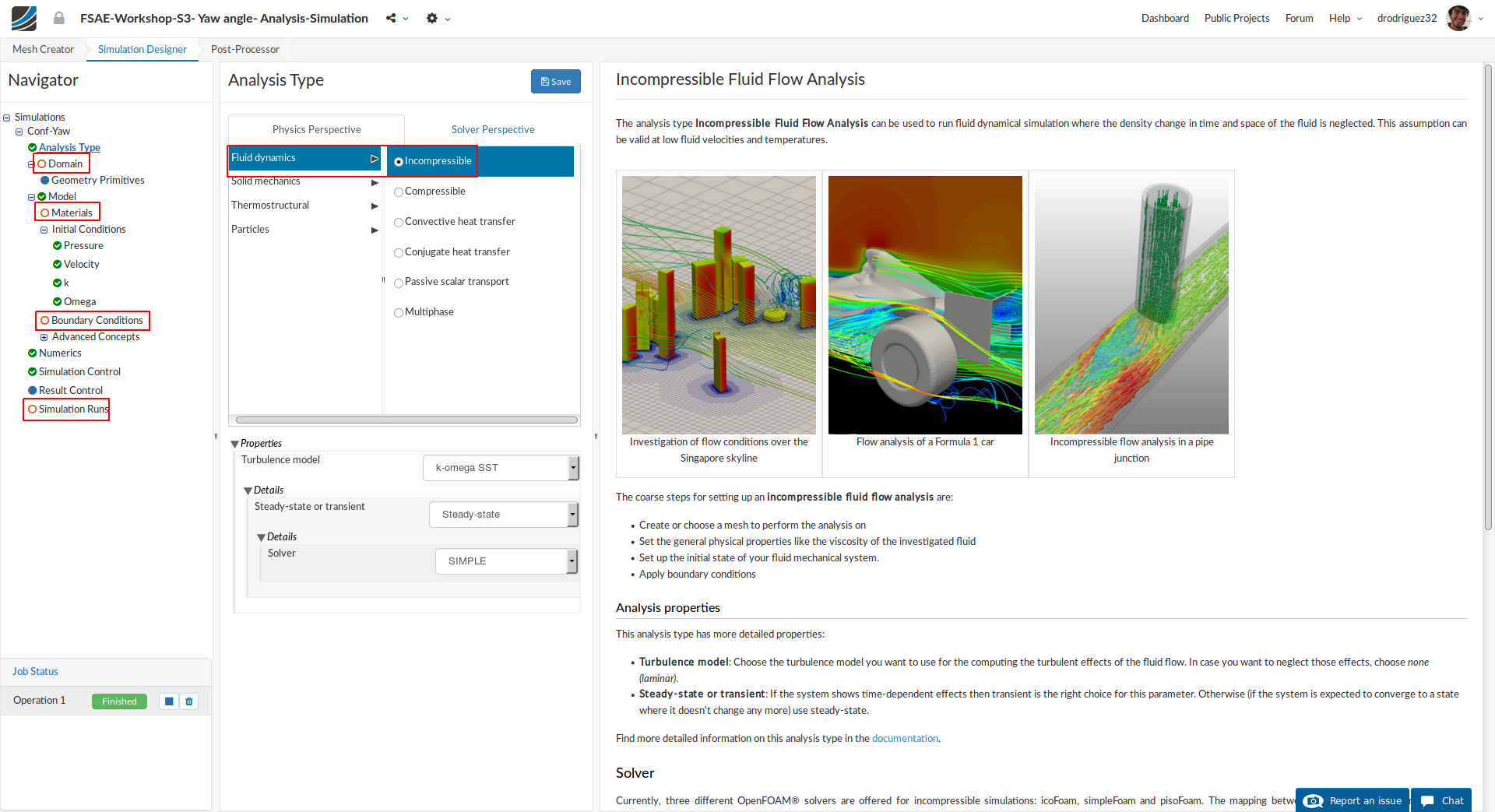
Under Analysis Type, switch to Fluid dynamics and then select Incompressible. You don’t have to change any other properties here.
Click Save
Once you save the analysis type, the items in the Navigator will expand. All of the red entities must be set up in order to perform a successful simulation run.
Domain
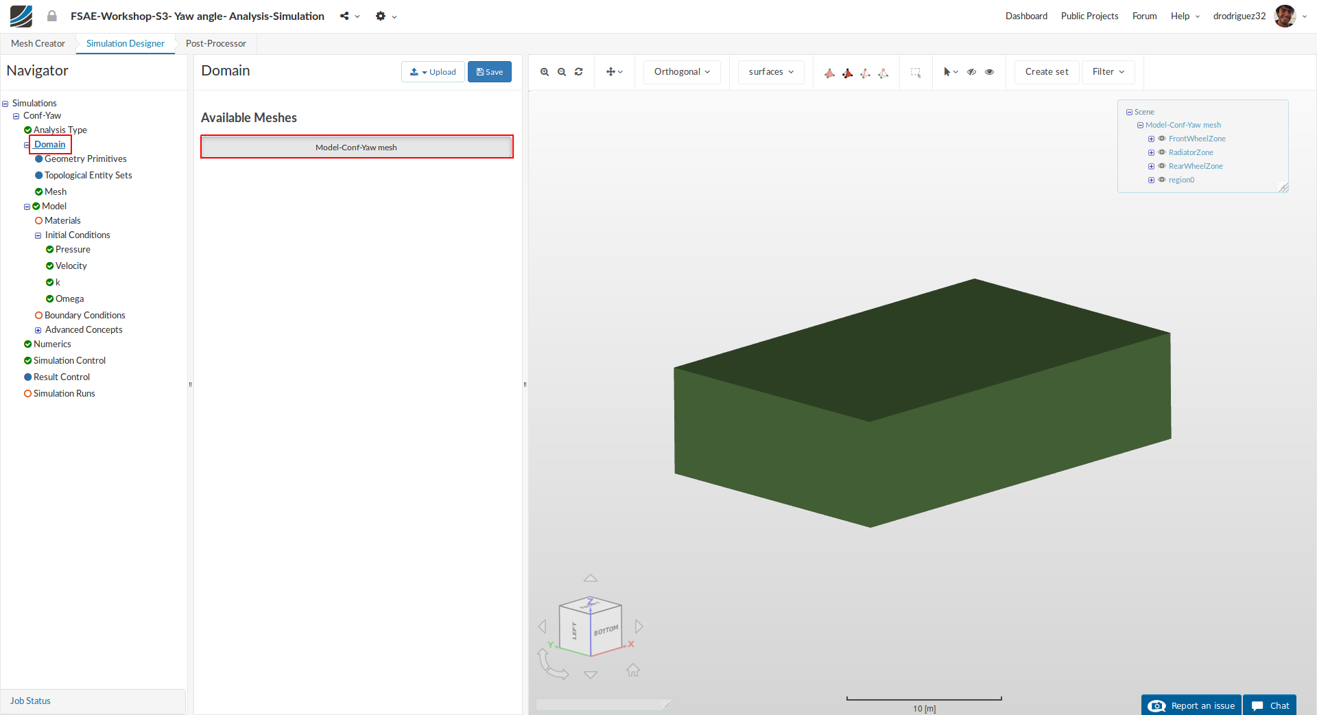
Proceed to the Domain item in the Navigator and select the mesh you just created. Then click Save. You will see the loaded mesh of the selected domain in the viewer. For the easier mesh handling, it is recommended to switch to the surfaces render mode in the top viewer bar.
Material
Next we have to define the fluid material.
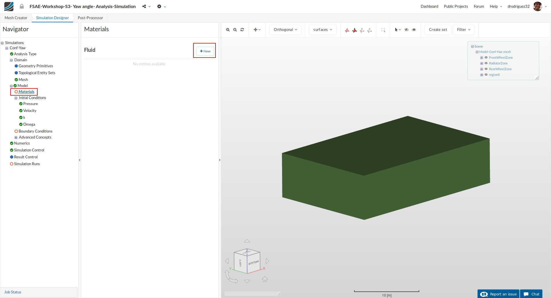
Go to Materials and click on +New
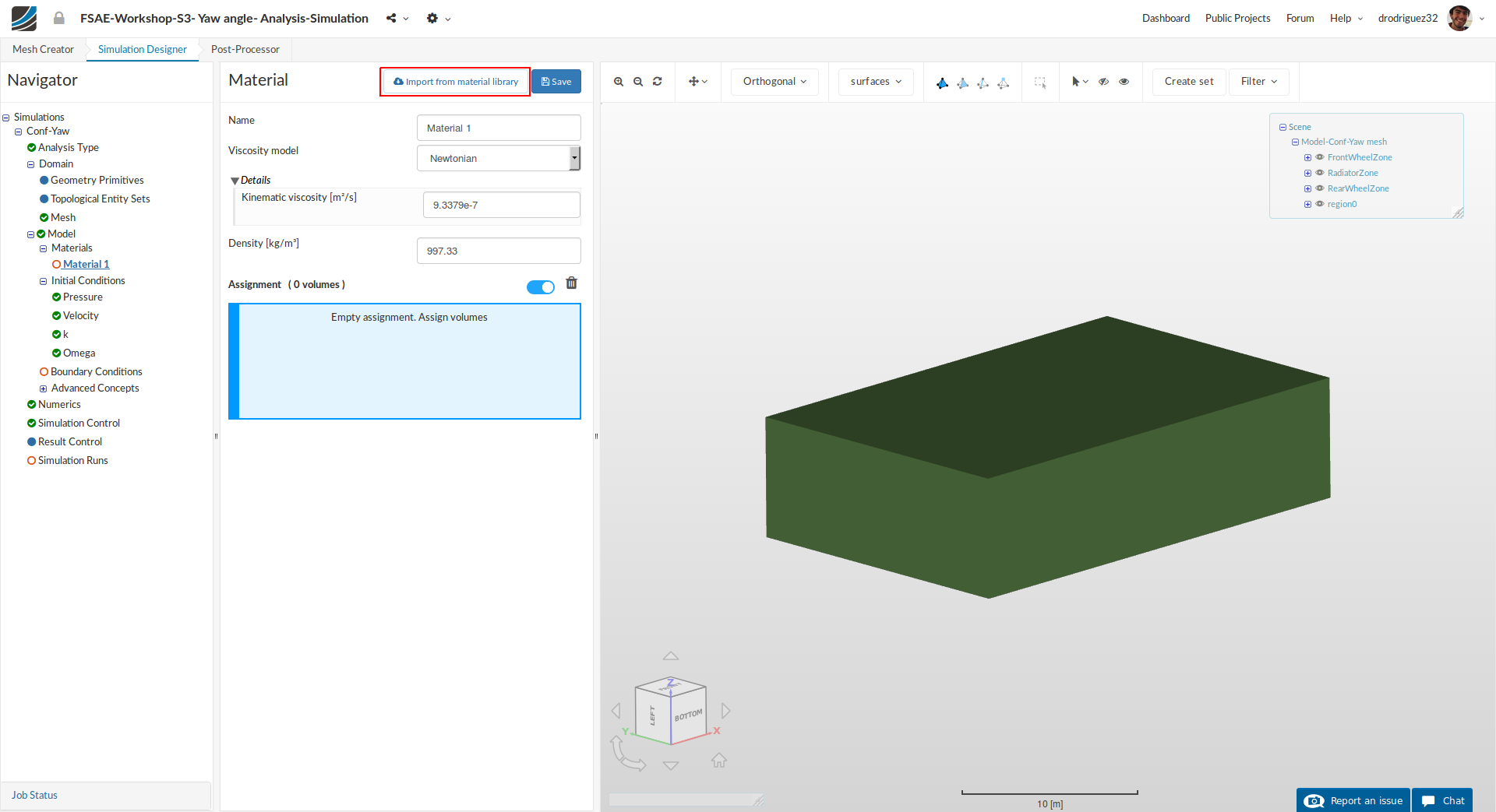
Click on Import from material library to import the desired material from the material database.
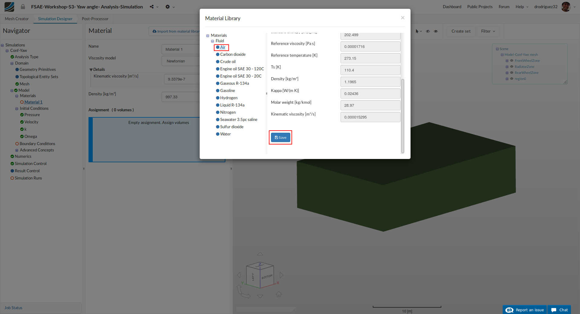
Select Air and click Save to import this material directly from the library.
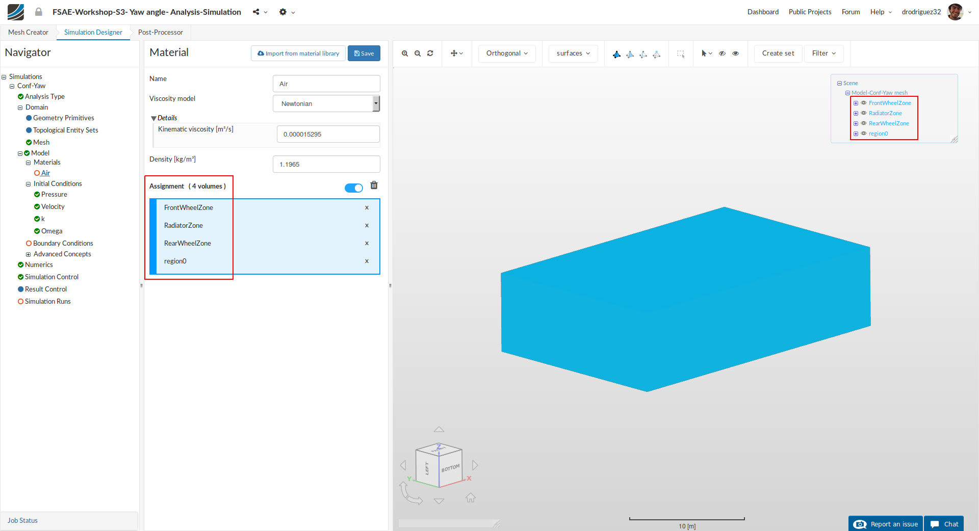
Select region0, RadiatorZone, RearWheelZone, and FrontWheelZone from the navigator in the right.
Then click Save
Initial Conditions
We will now proceed to change the initial conditions.
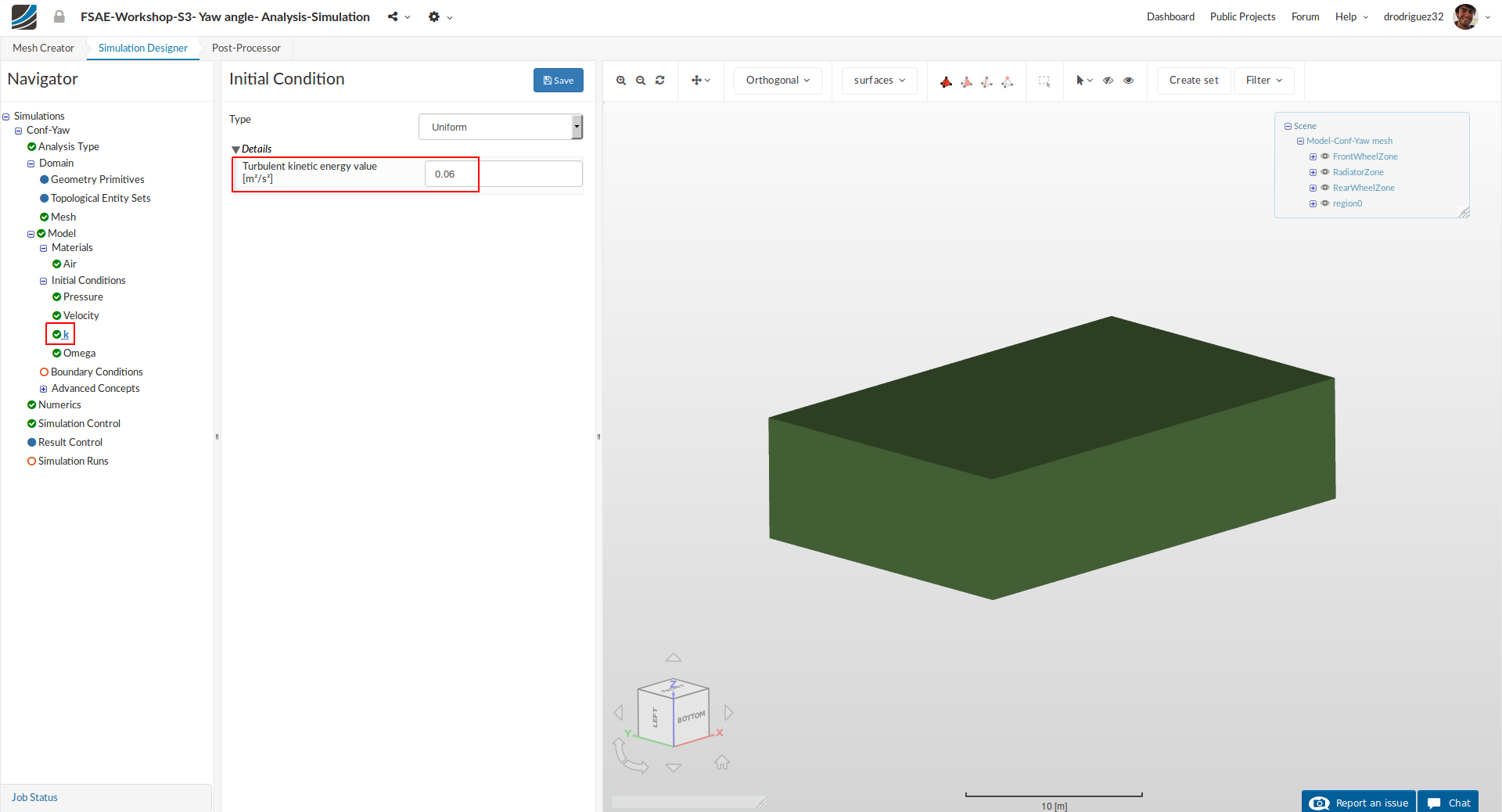
Go to k and change the Turbulent kinetic energy value [m²/s²] value to 0.06 and click Save.

Next go to Omega and change Specific turbulence dissipation rate [1/s] to 44.7 and click Save.
For a more detailed description on turbulence modelling please refer to the SimScale Documentation (Turbulence Models) or Part 1 of the Step-by-Step Tutorial Session 2 under Initial Conditions (Step-by-Step Tutorial Session 2 - Full Car Aerodynamics (Part 1))
Boundary Conditions
Now we will proceed to the most crucial and important section of the simulation setup: setting up the boundary conditions. This is simply telling the platform how we want the simulation to behave. But this time there will be a difference because we want to investigate the side wind effect, so we will customize the inlet boundary condition to control the angle of the free stream according to the car. We will then define the boundary condition for the floor, the roof, and the car (you may have noticed that we don’t have symmetry plane like in the previous session because we are working with the full car).
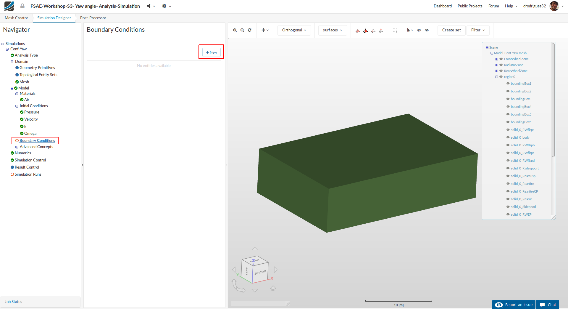
Go to Boundary Conditions and click New in order to create a new boundary condition.
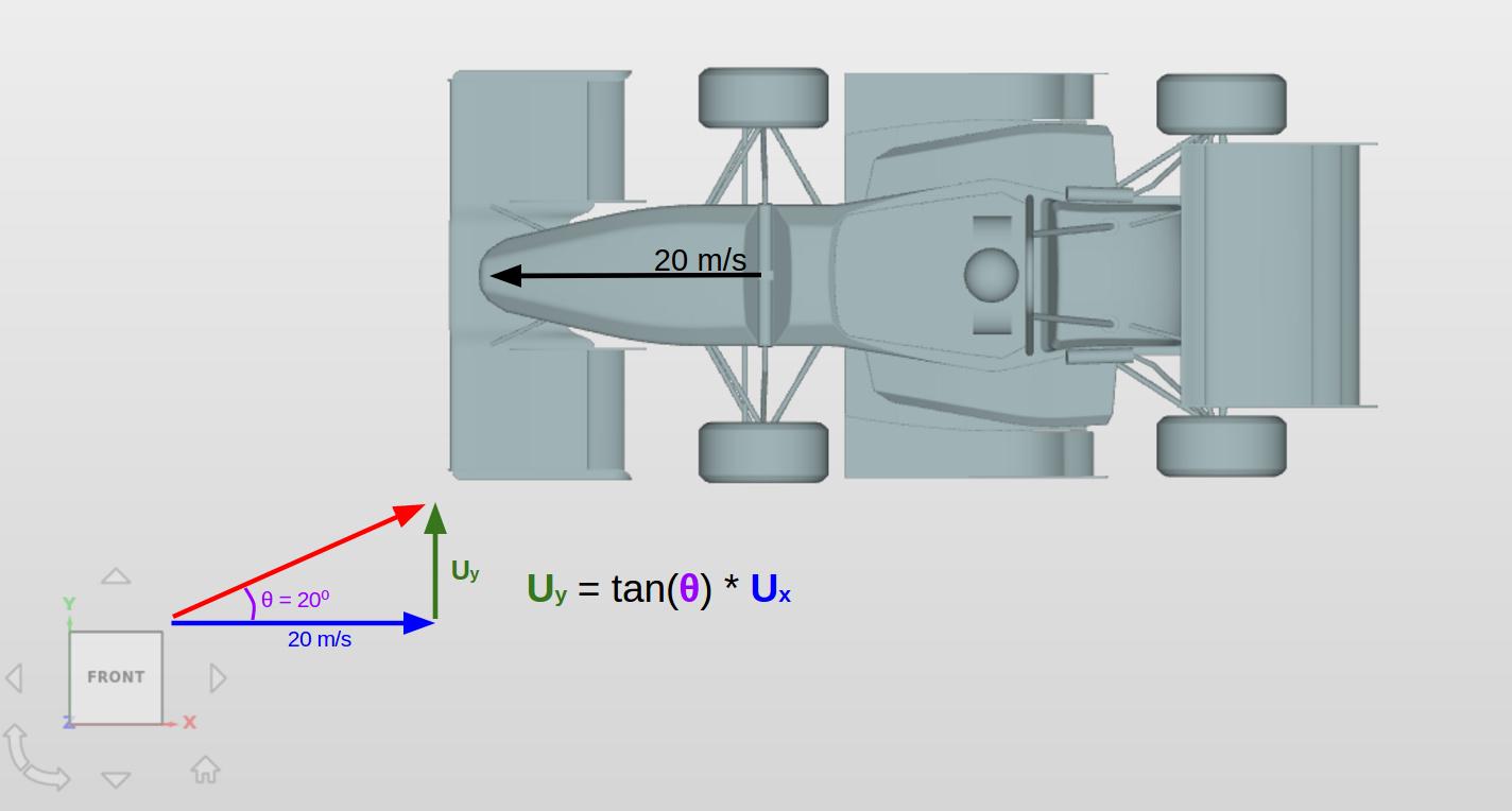
Inlet
Formula for calculating velocity components:
Setup:
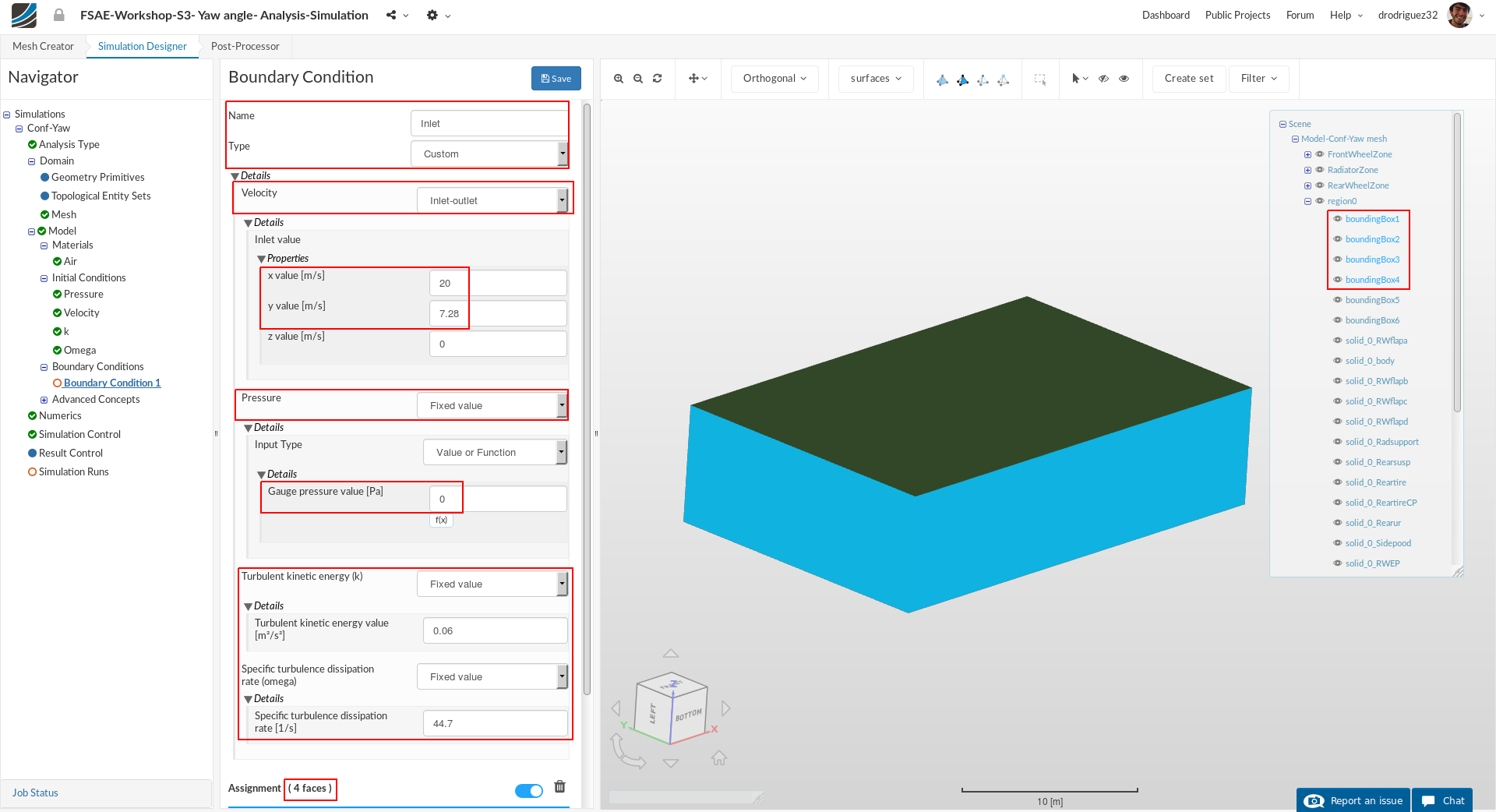
Name the newly created boundary condition to Inlet (optional).
Set the Type to Custom
Under Details select Inlet-Outlet for velocity
Then under Details > Inlet valve > properties we will specify the X and Y components of the velocity vector depending on the freestream angle of 20°.
We know that the car is travelling forwards at 20 m/s, so we have the X component of the vector. We also know that the yaw angle is 20°, so we can calculate the Y component of the freestream vector with trigonometric ratios (in this case we would use TAN like the above image).
The X value = 20 [m/s] and for 20° the Y value = 7.28 [m/s].
Take into account that you can also know the velocity of your car, the velocity of the side wind and then calculate the vector/yaw angle. In this particular case we simply decided to approach the problem from a fixed yaw angle scenario and thus we calculated the necessary side wind for that yaw angle to happen.
For Pressure select Fixed value and under Details > keep the value of 0 [Pa]
For Turbulent kinetic energy value [m²/s²] value and Specific turbulence dissipation rate [1/s] respectively under details enter 0.06 and 44.7. These values are the same we assigned in the initial conditions
Select all the sides of the bounding box. You should see boundingBox1, boundingBox2, boundingBox3, and boundingBox4 under Assignment.
Click Save
Roof
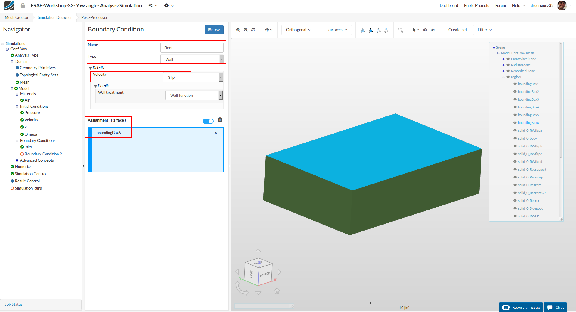
Create a new boundary condition named Roof (optional).
Change the Type to Wall and under details select Slip
Select the top wall of the bounding box (boundingBox6).
Click Save
Floor
We will now define a moving floor boundary condition.
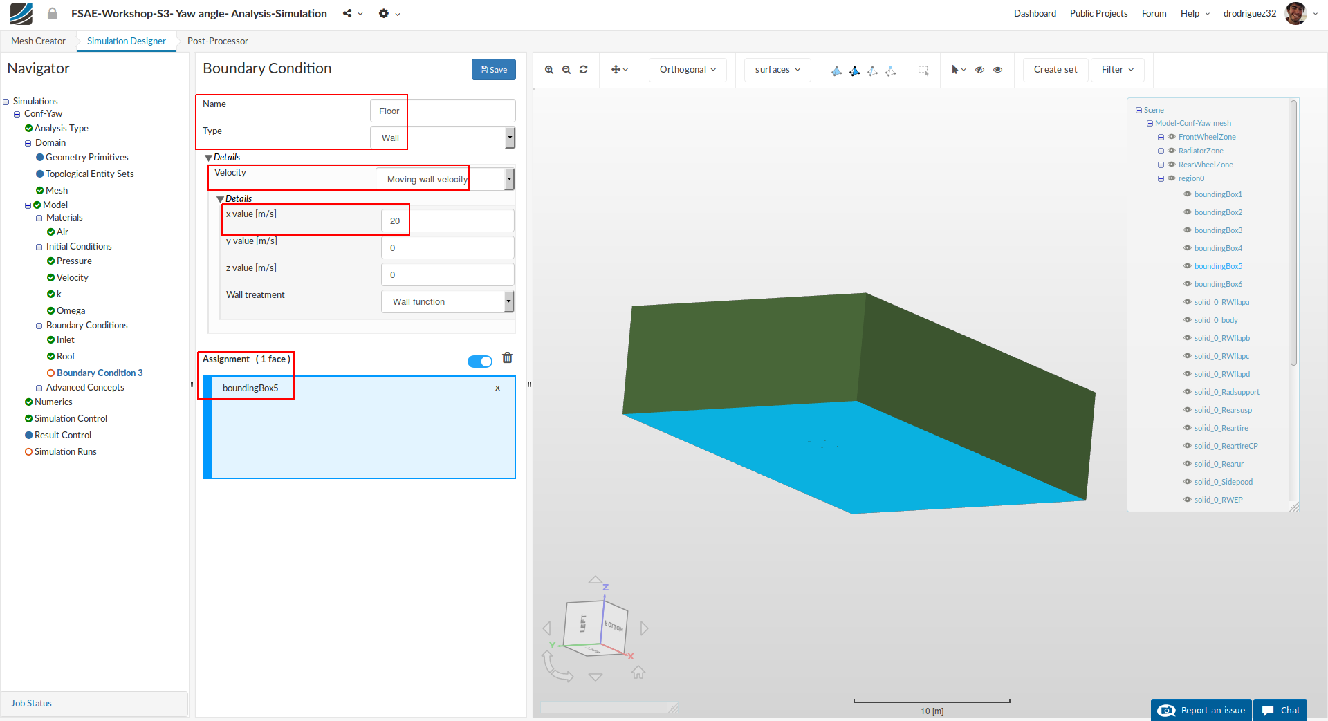
Create a new boundary condition named Floor (optional).
Change the Type to Wall and under details set Velocity to Moving wall velocity. The car is travelling in a straight line at 20 m/s, so this relative motion is what will be specified now.
Change the Type to Wall, under Details > Velocity select Moving wall velocity, and for the x value [m/s] input 20.
Select the bottom face of the bounding box (boundingBox5) - you should see it under Assingment.
Click Save to define the floor boundary condition.
Note
Note that in the previous session where we had no yaw angle the settings for the Floor matched the ones for the Inlet, but for this session they don’t. Applying the same vector to the floor as we did for the inlet would imply that the car is moving diagonally as if sliding - which is not the case. We have to maintain the condition that there is side wind, and thus in this case there is relative motion between the air and the floor in the Y direction.
Car
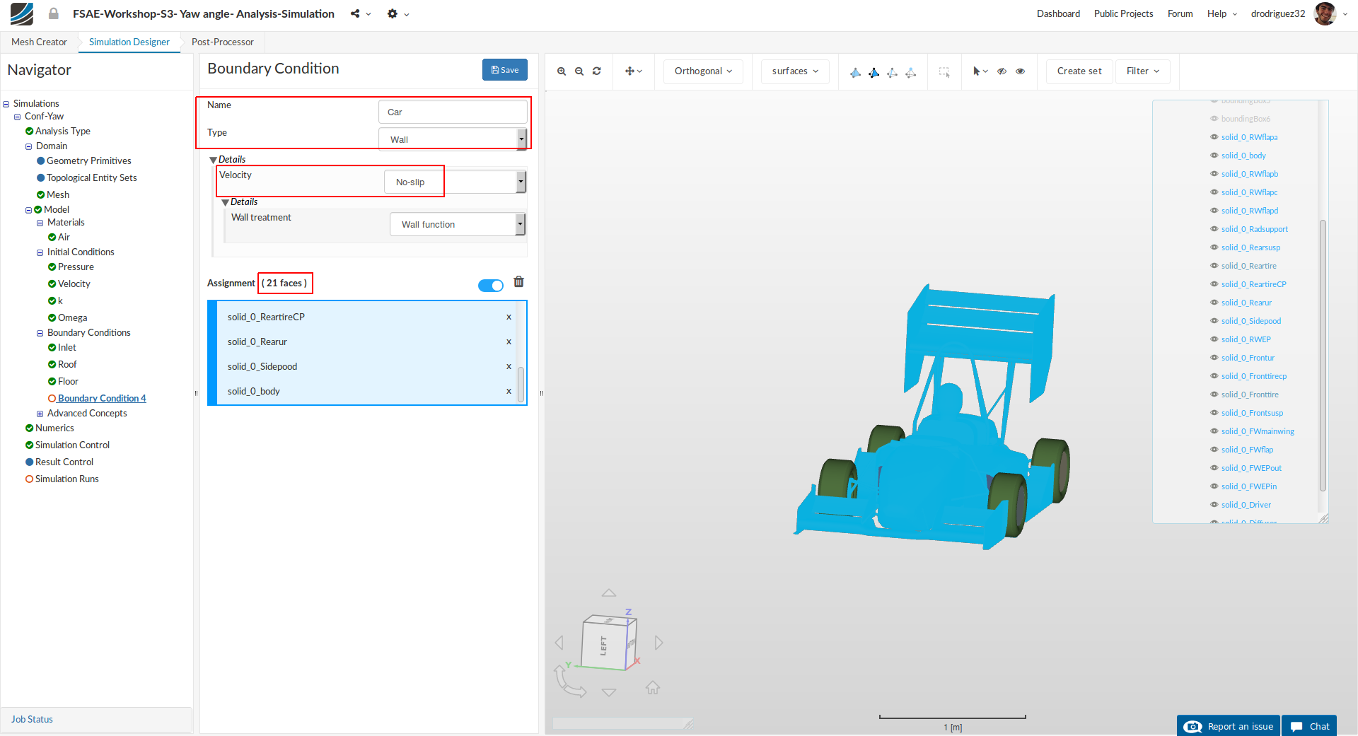
Create a new boundary condition named Car (optional).
Select all the entities starting with solid_0 except for solid_0_Reartire, solid_0_Fronttire
Click Save to define the boundary condition for the car.
Front Wheels
Next we will add a rotating boundary condition for the wheels.

Create a new boundary condition named Front wheel (optional).
Change Type to Wall and Velocity to Rotating wall velocity. Then change:
-
Origin x value [m], y value [m] and z value [m] value to -0.41566, 0.670378 and 0.219731 respectively.
-
Axis of rotation x value [m] and y value [m] to 0 and 1 respectively.
-
Angular velocity [rad/s] to -90.91
-
Then select solid_0_Fronttire
-
Click Save to register your changes.
Rear Wheels
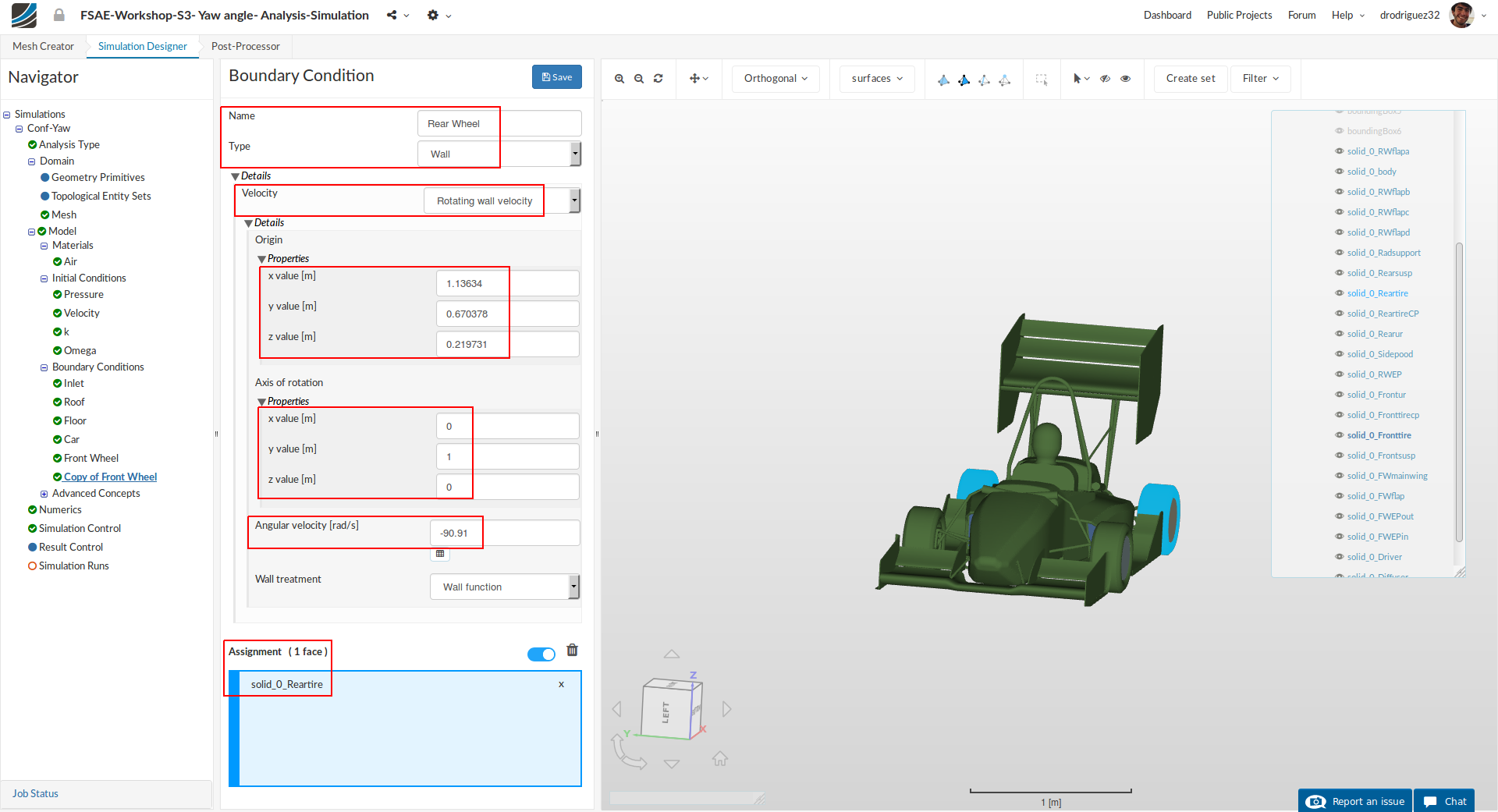
Duplicate the previous boundary condition by right clicking on it and selecting Duplicate. Rename it to Rear wheel (optional).
Change the Type to Wall and Velocity to Rotating wall velocity. Then change:
-
Origin x value [m], y value [m] and z value [m] value to 1.13634, 0.670378 and 0.219731 respectively.
a. Notice that the origin values for the y axis and z axis are the same as the previous boundary condition. That’s why it was better to duplicate it. -
Axis of rotation x value [m] and y value [m] to 0 and 1 respectively.
-
Angular velocity [rad/s] to -90.91
-
Then select solid_0_Reartire.
-
Click Save to register your changes.
MRF zones
For a more detailed explanation on MRF zones and the difference between MRF and Rotating Walls please refer to Part 2 of the Step-by-Step Tutorial Session 2 (Step-by-Step Tutorial Session 2 - Full Car Aerodynamics (Part 2)) or the SimScale Documentation (Rotating Zones)
MRF Front
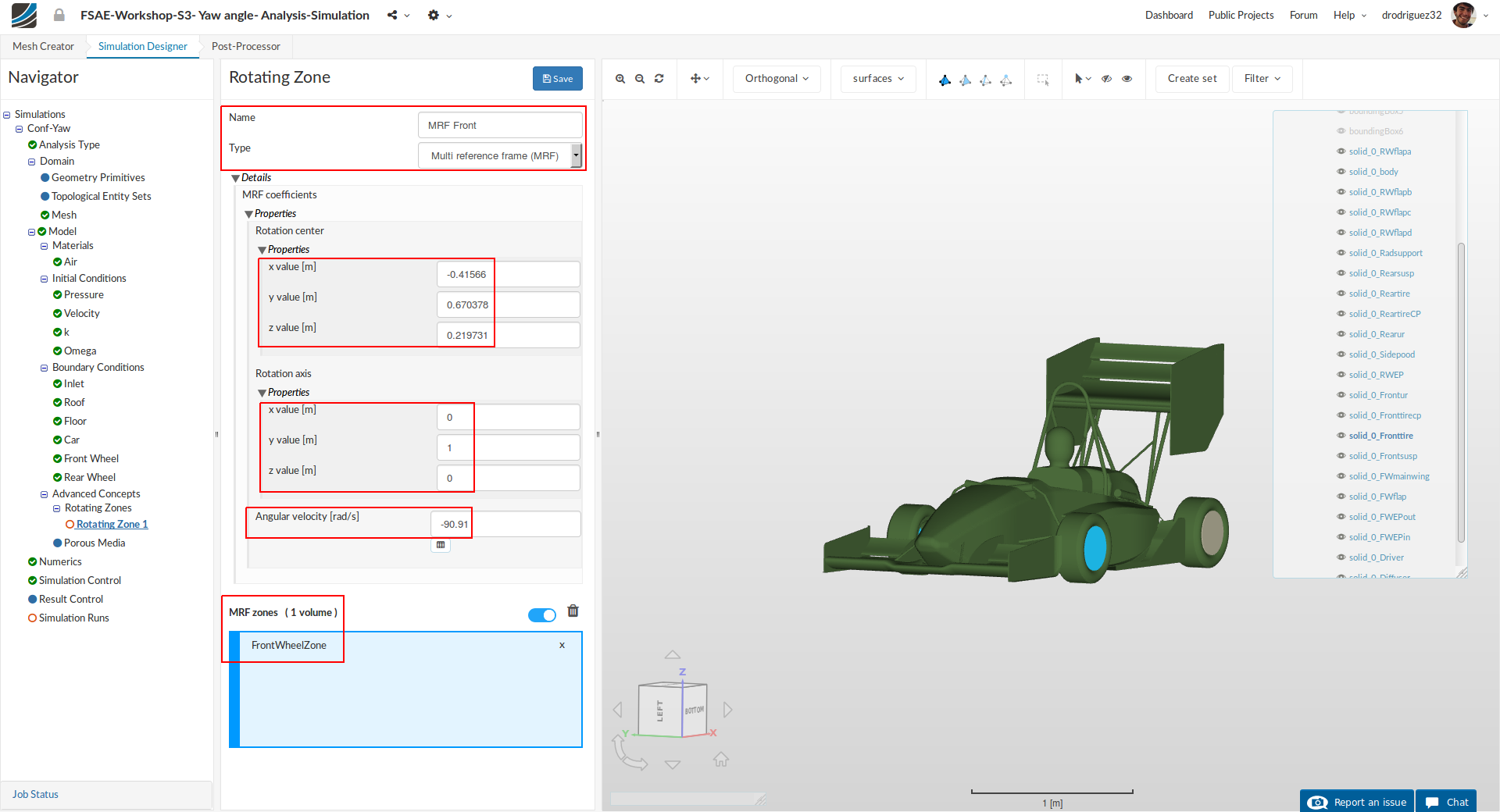
Add a Rotating Zones under Advanced Concepts named Front wheel MRF. Then change:
-
Origin x value [m], y value [m] and z value [m] value to -0.41566, 0.670378 and 0.219731 respectively.
-
Axis of rotation x value [m] and y value [m] to 0 and 1 respectively.
-
Angular velocity [rad/s] to -90.91
-
Then select FrontWheelZone
-
Click Save to register your changes.
MRF Rear
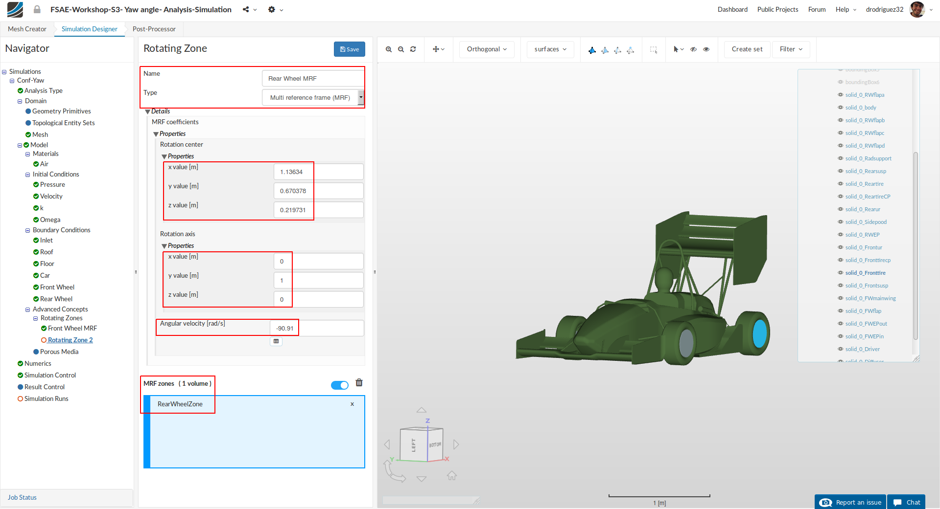
Similarly, perform the same procedure and create a new Rotating Zone. Rename it to Rear wheel MRF. Then change:
-
Rotation center x value [m], y value [m] and z value [m] value to 1.13634, 0.670378 and 0.219731 respectively.
-
Rotation axis y value [m] to 1
-
Angular velocity [rad/s] to -90.91
-
Then select RearWheelZone
-
Click Save to register your changes.
Porous Media
For a more detailed explanation on porous media please refer to Part 2 of the Step-by-Step Tutorial Session 2 (Step-by-Step Tutorial Session 2 - Full Car Aerodynamics (Part 2)) or the SimScale Documentation (Porous Media)
In this section we will define the radiator volume source via porous media.
Expand the Advanced Concepts tree item and proceed to Porous Media. Click +New to create a new porous media definition.
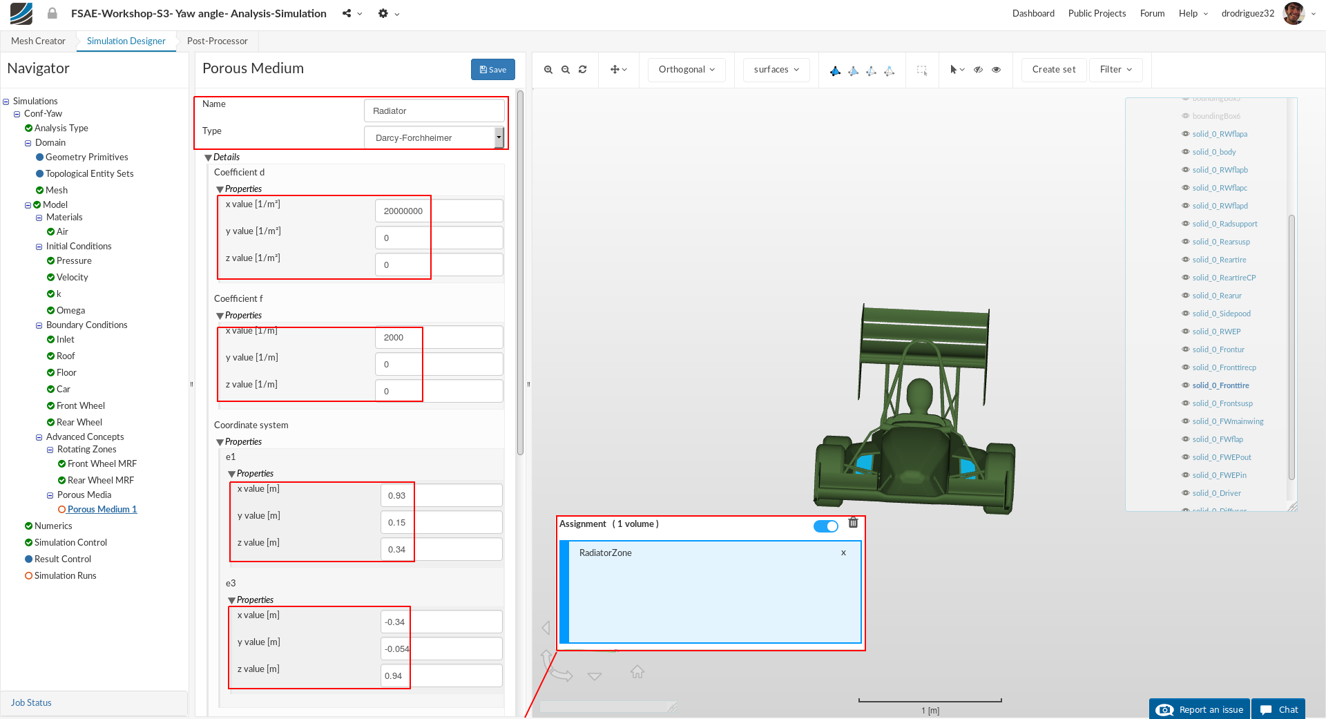
After creating a new porous media definition, you will be automatically directed to the properties panel. We will use the same simplification we used for the previous session, so input the following settings:
-
Name to Radiator-PorousMedium (optional).
-
Coefficient d x, y and z values to 20,000,000, 0 and 0 respectively.
-
Coefficient f x, y and z values to 2000, 0 and 0 respectively.
-
Coordinate system e1 x, y and z values to 0.93, 0.15 and 0.34 respectively.
-
Coordinate system e3 x, y and z values to -0.34, -0.054 and 0.94 respectively.
-
Select RadiatorZone
-
Click Save to register your changes.