I want to analyse the lift and drag for a wing sail. Therefore I have created this project:
Somehow I do not get valid results. There seems to be a mistake in the simulation setup, but I can not find it.
I want to analyse the lift and drag for a wing sail. Therefore I have created this project:
Somehow I do not get valid results. There seems to be a mistake in the simulation setup, but I can not find it.
HI this is Fillia from SimScale Support.
Your boundary conditions and general set up look alright, so personally I would focus on the mesh and domain.
Try using this tutorial as reference: Tutorial: Compressible CFD Simulation of a Golf Ball | SimScale
Of course this is compressible analysis, but you can get good information about the Enclosure’s size ( Figure 4 ), how to apply Symmetry, and how use the Standard algorithm for mesh generation.
Try to recreate the mesh refinements of the tutorial as well, and make sure you monitor the y+ values:
After each mesh is generated, you can check the quality using this guide: How to Check and Improve Mesh Quality | SimScale
Best regards,
Fillia
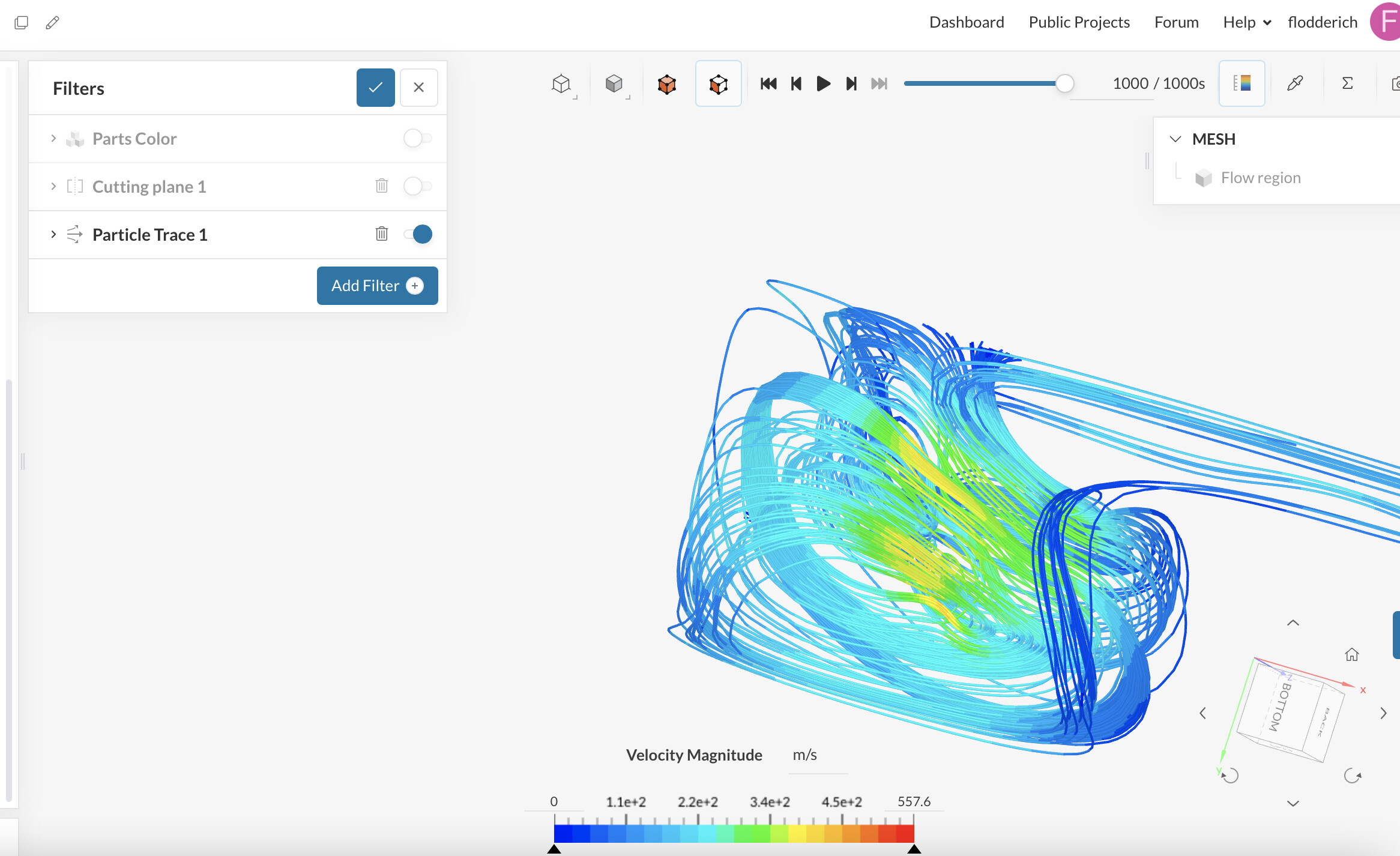
Exactly, these high values can be created by bad elements inside the mesh, as the boundary conditions do not seem to be unrealistic. There is a method described here with which you can isolate the cells with high values (through isovolumes), so you can find out what areas are problematic: How to Check and Improve Mesh Quality | SimScale
Check section 2.2
Best regards,
Fillia
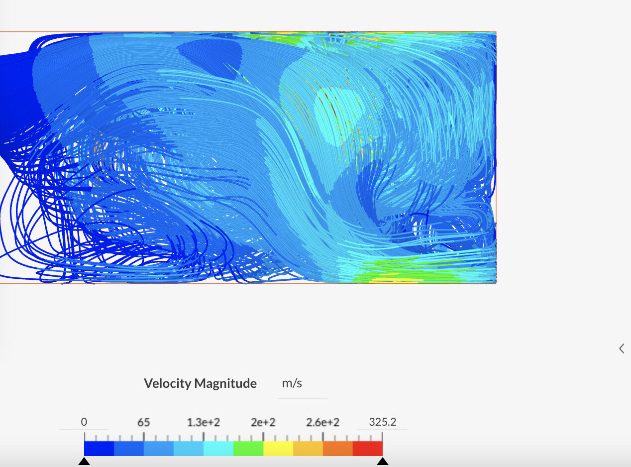
I will check on that. By the way, is it normal that the flow is going upwards and not in a straight line ?
You should expect a behavior close to this: Compressible Flow Around a Wing | Tutorial | SimScale
But this is a compressible Simulation, because it is an aircraft wing. Mine is a wing so a sailing vessel, so the maximum speed will be the wind speed + boat speed. Making it not more than 30m/s. That’s why I chose incompressible.
Then you can also check the vehicle tutorial: Aerodynamic Flow Behavior Around a Vehicle Tutorial | SimScale
What I mean is that the streamlines should remain close to the body for this type of application, especially for a single wing, does this make sense?
This is because of the bad cells of your mesh, please check this documentation I sent you before (How to Check and Improve Mesh Quality | SimScale) to refine it further ![]() Cheers
Cheers
Is that project private? I’d like to take a look to help you
That’s a steady-state solution, right?
I see the velocity values are very high near the upper and lower boundaries. Are you using something like freeStream boundaries?
I disabled the private function. You should have access to the project now.
Yes, it is a steady-state-solution.
Ok thanks, many things:
1 - Do listen to @tsite advise and improve your mesh quality. Use a structured mesh (hex-based). A good mesh is arguably the most important part of the simulation process. No matter how powerful is your computer or accurate is the CFD method used, you need a good mesh to achieve good results.
2 - Poor quality grids need a very robust interpolation scheme. Use a bounded Gauss upwind first (always) for div(phi,U). If it works well, you can jump to a second order-accurate scheme (gauss-linear upwind).
3 - The solver needs to solve a complete fluid dynamics case but we aren’t giving it much help. Do set an initial velocity in the Ux direction to give the solver much-needed help to come out with the solution. The initial velocity of the internal field should be the same as used in the inlet boundary.
4 - While using slip-walls as boundaries is not a bad approach, it is much better to use a freestream boundary, unless you are simulating a wind tunnel. SimScale has already prepared some documentation for it: Velocity Inlet & Velocity Outlet Boundary Conditions | SimScale .
4- If the object (wing) starts at the wall, it is much better to use a symmetryPlane.
(1), (2) and (3) are or may be error-generators. (4) and (5) are improvements.
I hope this helps,
Regards,
J.A. Gutiérrez