Here, I am trying to validate the flow around the vertical plate, i…e, a flat plate perpendicular to the incoming flow. There is no analytical solution to it.
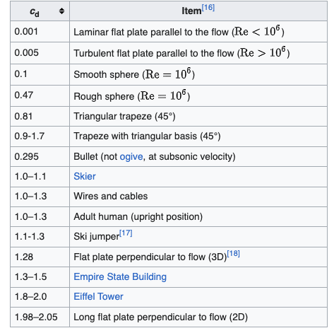
However, based on various numerical and experimental results, the value of Cd is expected to be around 2.
Here, I have a flat plate of 0.1 m long, considering it to be 2D. The specifications could be found in the following link:
I tried changing various parameters, and models, yet getting around 0.8-0.9. Can someone say where I am going wrong or is there an explanation for this ?
Hello @athiram , and thanks for posting your question on the Forum!
First of all, comparing the drag coefficient with the 2D experimental/empirical results may not be the best approach. 2D case assumes that the span of the plate is infinitely long, which is not the case in your current setup. I believe the flow should be flowing through the upper and lower sides of the plate, rather than the sides.
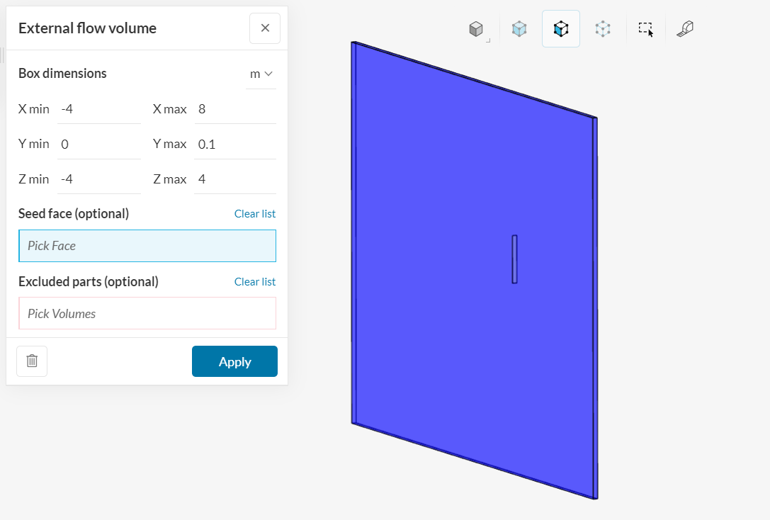
To simulate a 2D like model, the model should look like the following:
Thanks for the response. However, I am slightly confused as well.
Here the domain is set such that it is technically 3D, however the boundary conditions have been set such that left and right sides of the domain is set to “symmetry” which makes it equivalent to that of infinite span, isn’t? is my understanding wrong?
The flow is made flow through the front and back sides of the domain, because the flat plate is to be kept at angle of attack =90 degrees, or in other words, flow over a vertical plate.
From the flow set up, that you pasted, I am assuming that the flow is through the top and bottom of the domain isn’t? Also in such case BC for the front and back sides of the domain will be set to symmetry ?
If that the flow set up, it will equivalent to the flow over a flat plate at angle of attack =0 degrees?
I understand your point, then in this case yes symmetry boundary condition should work as intended indeed. My point of understanding was to keep the flat plate in 90 degrees angle still but to use the length of 1 meters.
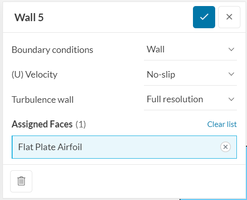
Thanks for clarifying this for me. In this case, I would say let’s focus on the suggestions given in 2,3 and 4. I would start by hex-dominant mesh approach. One other idea, I could think of, to improve the solution is switching to a Full Resolution wall boundary condition rather than wall functions approach.
Wall functions are most of the time should give good approximations when doing comparison studies, however full resolution approach may be required when we’re performing validation studies.
This approach requires much denser elements near the walls though which will increase the computational demand either, to ensure we have y+ values below 1. This can be ensured by using Inflate Boundary Layer refinement under the mesh settings.