I want to use an air speed not perpendicular to the ‘Velocity inlet’ face (using the x and y velocities/etc. using the ABL method: Smoke Propagation From a Chimney | Tutorial | SimScale ). I have on the opposite side a ‘Pressure outlet’. The remaining faces of my Flow region are: vertical and ceiling and ‘Wall/slip’, the ground is ‘Wall/non-slip’.
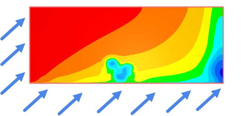
The problem now is that if I simulated an non-perpendicular inlet velocity, the right wall shades (blue) and left wall stop (red) the air:
.
How can I solve this? I was thinking of making the Inlet face much wider, is that the way, or should I have different boundary conditions for the Wall; or should I have two Inlet faces (also the right vertical wall)?
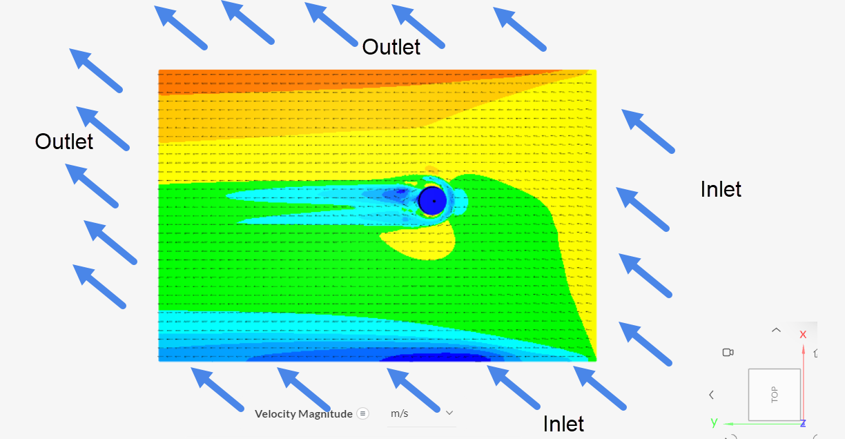
Hi, the usual approach would be to also set one of the side faces as an inlet and the opposite side face as an outlet, similar to what was done in this tutorial.
Depending on the sizing of your flow domain, you might have to make the side walls more distant from the region of interest (it’s difficult to tell just from looking at the image that you posted).
Sorry, I should have explained better what I had in the picture. This was a crosscut in x plane, looking from the inlet face. So the air was flowing under an angle of 12degrees into the monitor.
The flow region walls on left and right are ‘slip’. As the wind blows into the inlet under an angle.
I can provide the project, but do I need to make it first public?
Hello Dale,
Just to be sure (being novice in this field): As I am looking at velocities behind the tree, are these (wrong) lift and drag forces (on the object?) important for my evaluation?
By the way in my first 3D object is symmetric around its stem, so in that case it certainly is not a problem, or am I mistaken? I am now also testing another tree-model (from goncalves), which is not symmetric around its stem, there it might be of importance for the velocities behind the tree?
Sorry for these questions?
All the best,
A velocity is a vector which has a direction associated with it and a speed would be a scalar unit with no direction associated with it. Lift and Drag are specifically defined in aeronautics and you would only want to address them if you add a ‘Forces and Moments’ (or less likely ‘Force and moment Coefficients’) results item to your simulation output if you were trying to tell if the tree may be blown down or lifted out of the ground. Also you have only shown plots of Velocity Magnitudes so far so you can’t tell from which direction the wind is blowing unless you add some streamlines to show the direction.
Dale
Thanks for your feedback. Much appreciated. At this moment I am only trying to match an article’s velocity (magnitude), so the direction will be in the future (although I look a little at it).