Recording

Homework submission
Your homework for this session is to design your own front wing for a Formula SAE car, and test it using SimScale by following the same setup and steps as in the 2nd session.
Submitting all four homework assignments will qualify you for a free Professional Training (value of 500€) as well as a SimScale Certificate of Completion.
To submit your homework assignment, please generate a public link of your project (Sharing a Project)
Homework Deadline: October 24th, 11:59 pm CEST
Homework Extension
Hey everyone, we have reviewed the comments on the tutorial and have decided to accept homework submissions until the 27 of October at 11:59PM CEST. We will be accepting homeworks until the end of Friday. Be warned, the homework link will not be changed, and thus when you click on the homework submission link you will still see the old deadline.
We hope this gives you time to submit some really awesome homeworks!
Click Here to Submit your Homework
Outline
-
Introduction
-
CAD Models
a. Car without the front wing (STL)
b. Reference Geometry (STEP)
c. Reference Wing (STEP) -
Goal
-
Advice
-
STL File Export
-
Merging STL Files
a. Using Script
b. Using Text Editor -
Creating a Project on SimScale
-
Common Mistakes/Problems
-
CAD Tool Specific Videos
a. Autodesk Inventor
b. Solid Works
c. CATIA
d. Siemens NX -
Recommendations About Comments
Introduction
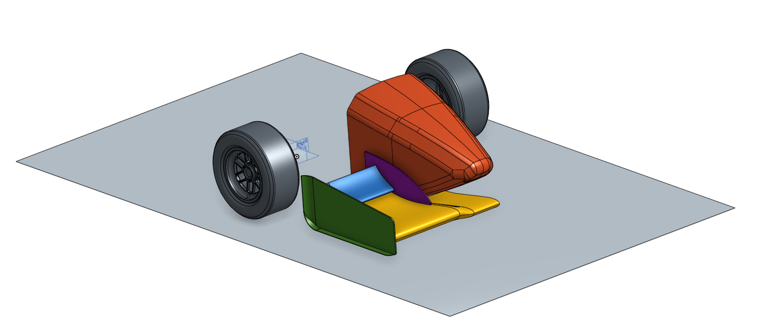
In this last session, we want to challenge you and see the skills that you have acquired during the course. For this exercise we want you to design your own front wing for Formula SAE, and test it using SimScale by following the same setup and steps in the 2nd session.
Your task is to design your own front wing and combine it with an existing car model that we have used in the previous exercises.
To start this exercise, you first need to have your own CAD software to model the front wing. Due to the variety of CAD tools available, with the help of our sponsored FSAE teams we have created a series of videos that quickly explain how to import, export, and merge all the files for four of the most common CAD tools.
You can download the car model without the front wing by proceeding to the next section
CAD Models
Important Note - This tutorial provides you with two different files:
1. Car model without front wing (STL)
This is the model you will attach your front wing to and the one you will use for your simulation as the STL file format has very high quality surfaces. As discussed in the fourth video lecture, we recommend that you prepare a STL master model for your own CFD process with SimScale.
Car model without front wing (STL)
2. Reference Geometry
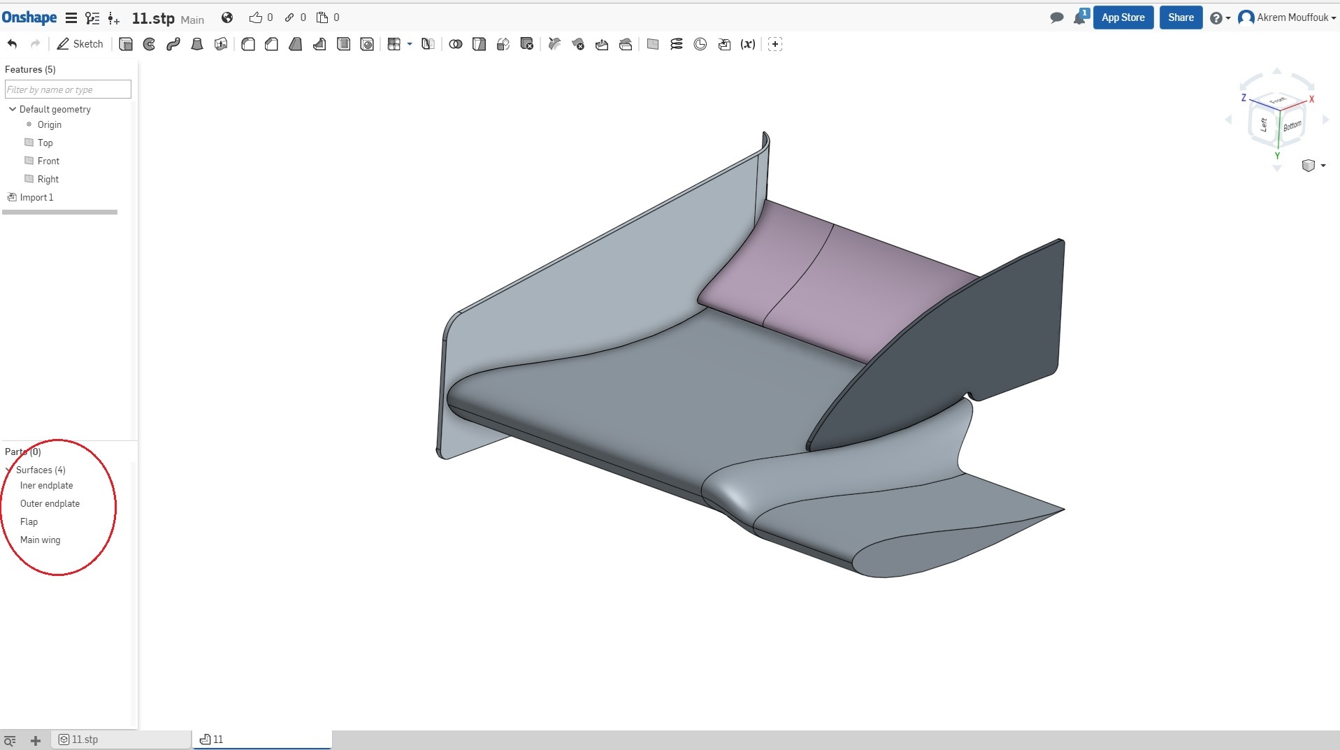
If you already have a wing design, we provide you this reference geometry of the nose, front wheels, and floor as a STEP file you can import into your CAD tool. With this you can make sure that your front wing is in the correct position before merging it with the whole car. Please make sure that you create the each wing component as a separate part/solid so that you can export each component individually as an STL file to be merged with the car.
3. Reference Wing
For those users who don’t have their own wing design and those that don’t have extensive experience with CAD modeling to create a wing from the start, we will provide you a STEP file of the front wing used in the first session. With this you should be able to get an idea on how to start, you can obtain the airfoil profiles used and adapt them to your new design, etc. But remember, the whole point of this homework is to submit your own design
Goal
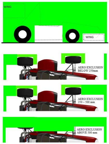
The idea is to create a better design than the existing one by creating more downforce with higher efficiency (i.e. can you produce less drag?) within the FSAE regulations.
Advice
For a successful simulation we suggest the following things:
-
Make sure that you create a clean geometry This means that you have to make sure that your model is a watertight, closed volume (**no open surfaces or edges). Be sure to avoid intersections and overlapping of surfaces when you create your CAD model.
-
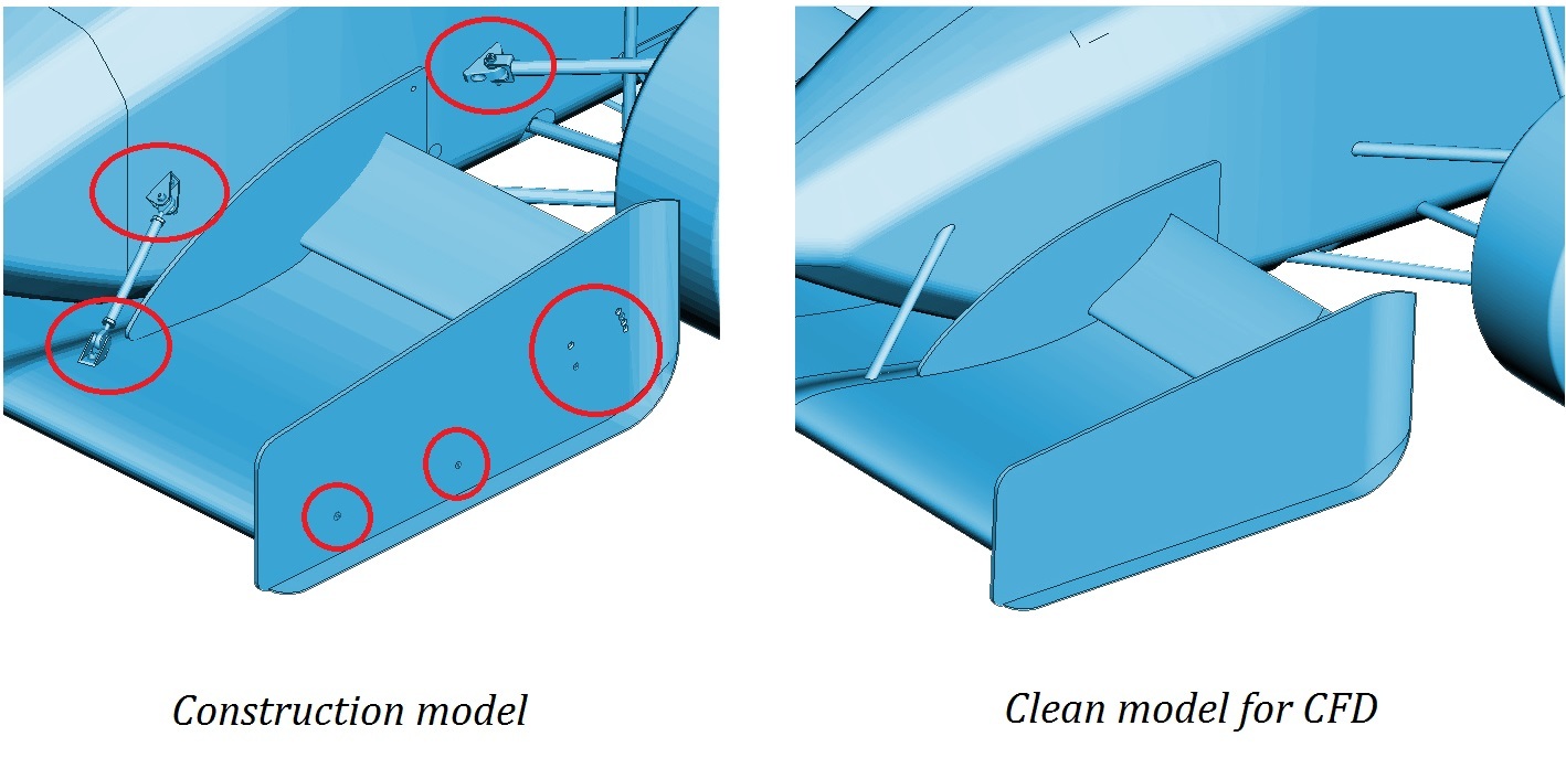
If you have an existing model and you want to test it, first defeature it and remove all of the construction details such as screws, bolts, and logos. (See image below)
To run the simulation on SimScale, it is recommended to use an STL file, that’s why you have to convert your CAD model into an STL model. In some CAD software when you export an STL file, you will lose the identity of the parts and solids, and you will have only one solid for all the parts.
Thus, it is important to follow the following steps to make sure that you will have an STL file with different parts, where you can apply different mesh refinements levels.
Creating your CAD model with different parts
Reference Model: Downloadable version of the Front Wing
STL File Export
Exporting a file depends on the CAD software that you are using, but here are the most common approaches to export different STL files for different parts.
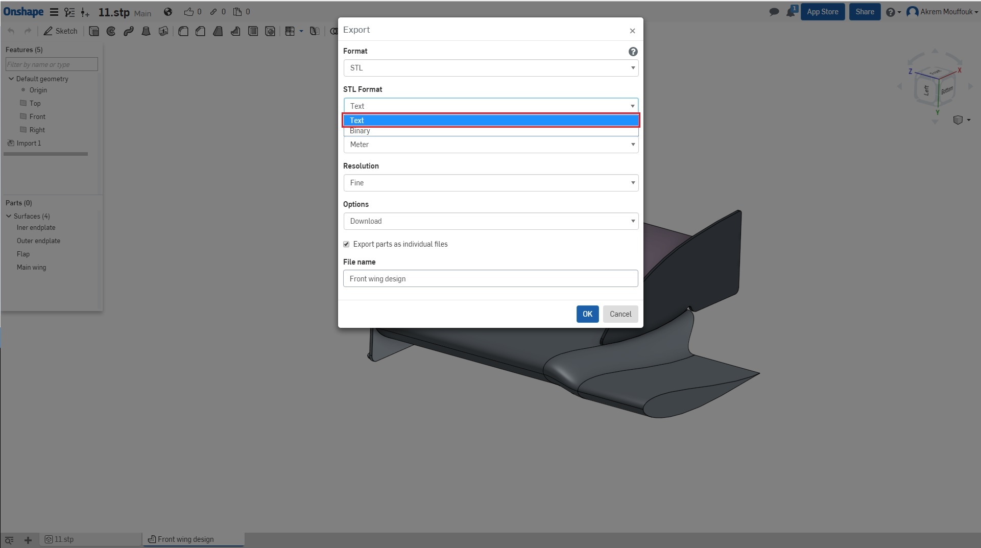
Some software keeps the same identity of the parts using colors when you convert the CAD model to STL model, and if you are using this kind of software you will not have any problems. Adjust the tessellation of your surface to high quality tessellation, to give an accurate representation of the curvatures. For STL files, there are two types: STL ASCII and Binary. Please choose the STL ASCII format, name your file, and export it.
For other softwares, you have to export a different file for each part.This can be done in two ways:
-
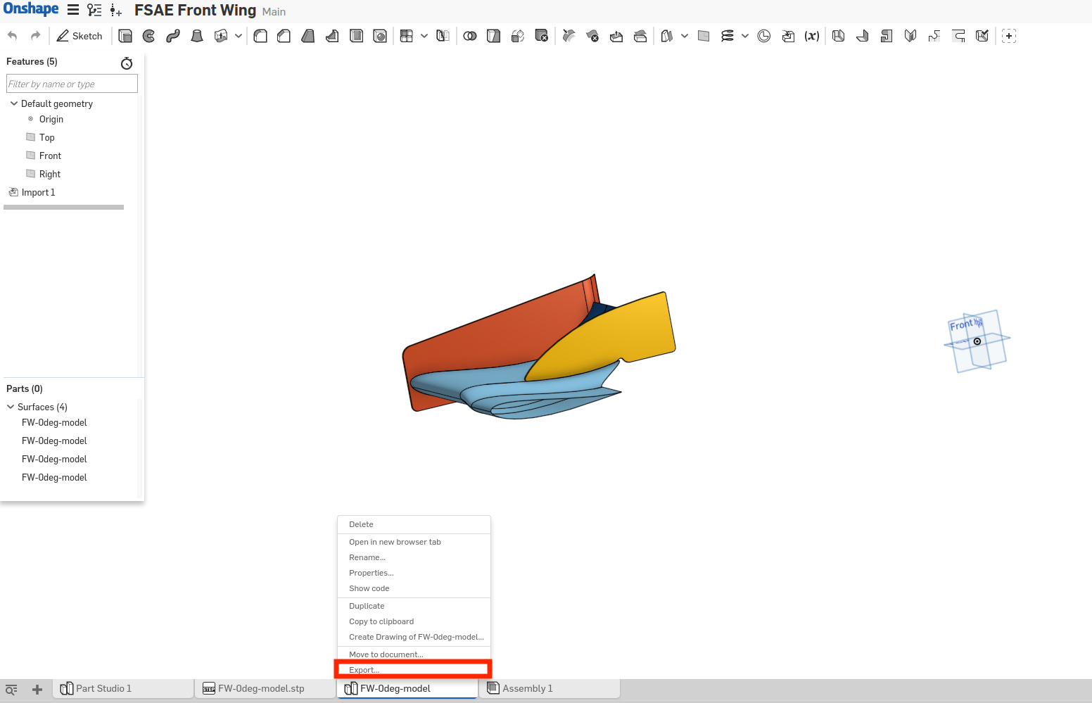
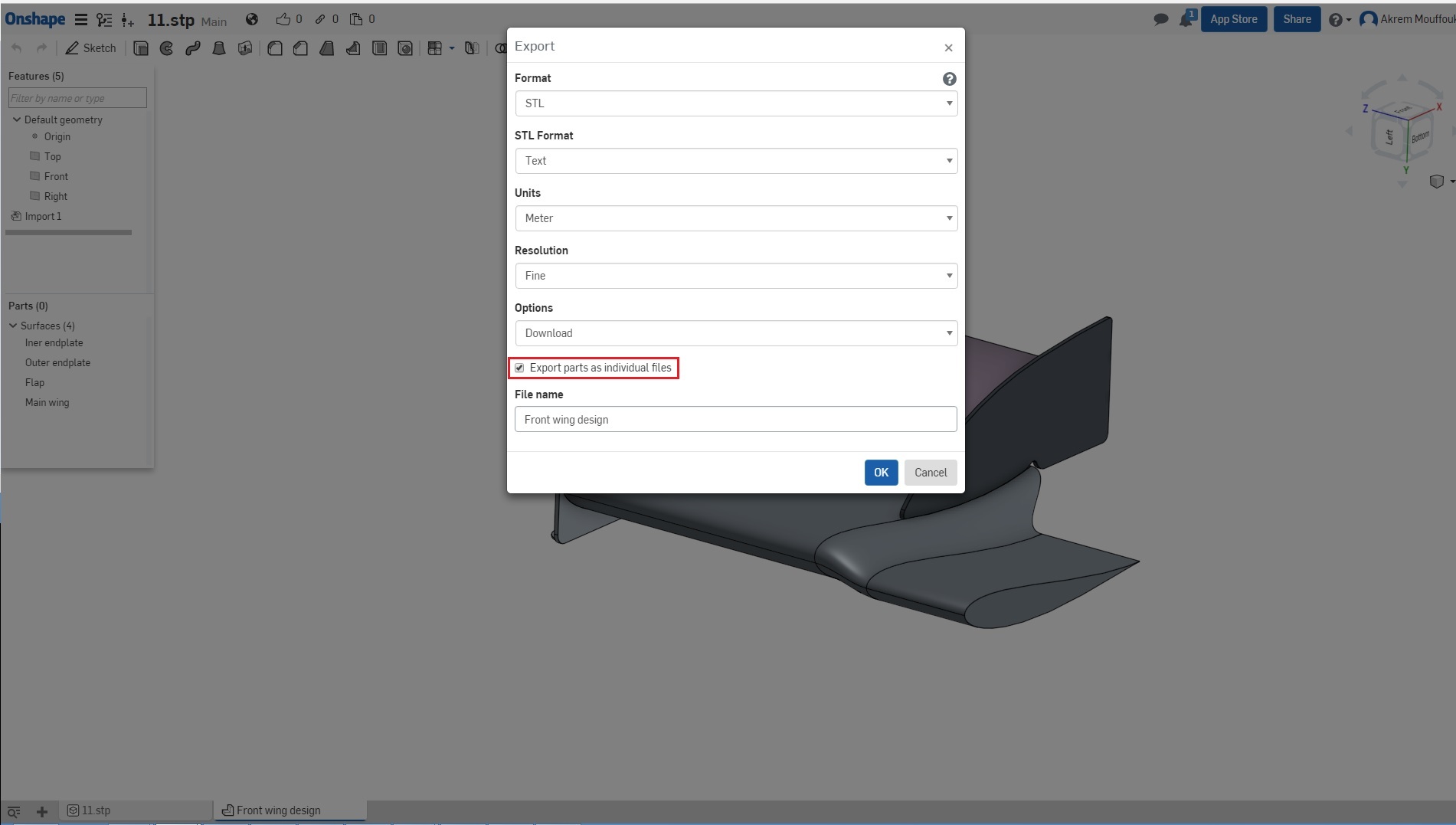
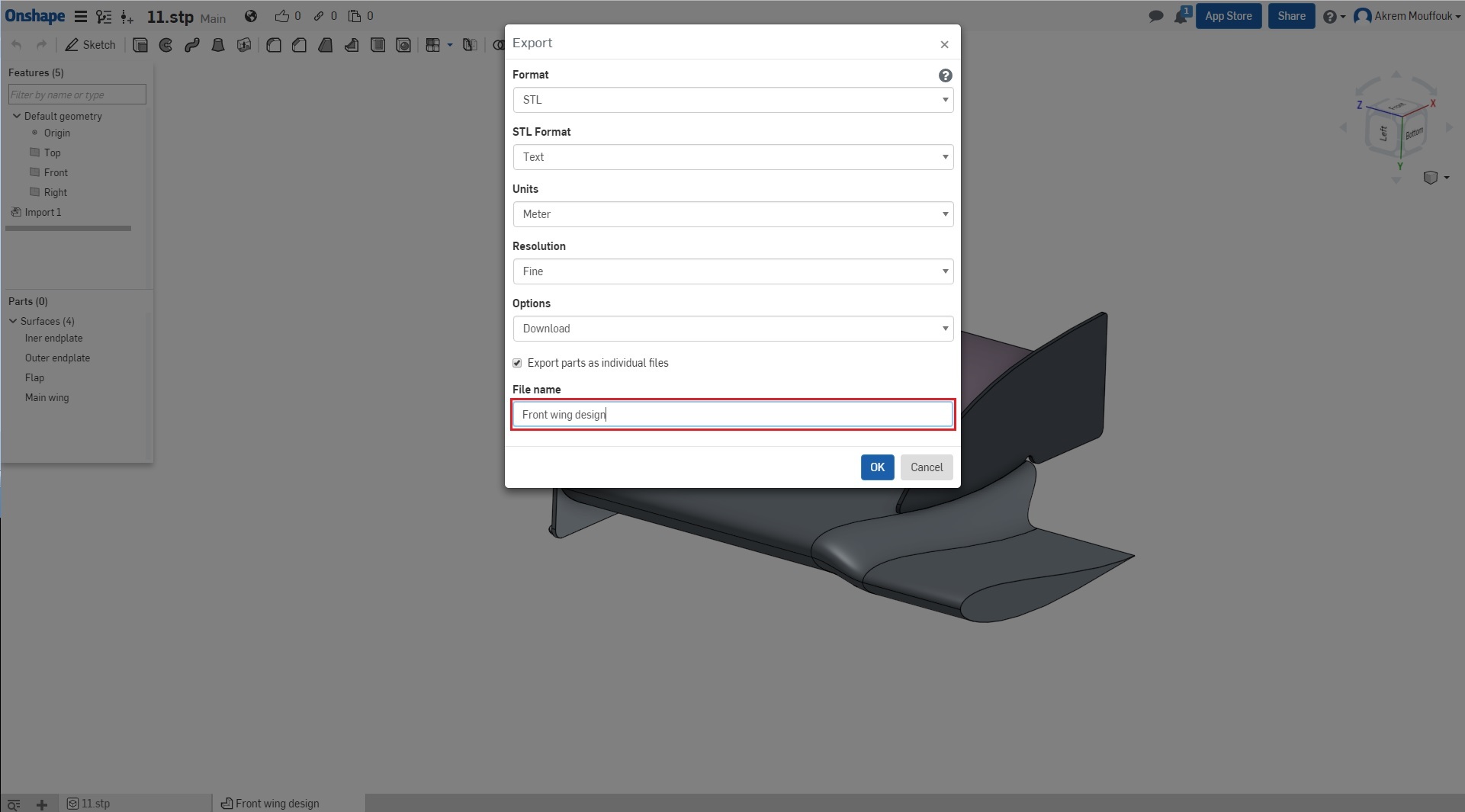
By selecting the specific part and exporting it as a single part per file. Again, it is important to adjust the tessellation to high quality and the Format to Text (option in Onshape renamed from ASCII to Text). Then name the file and export it to a specific folder.
-
Or you have to hide all the other parts, and keep only the part that you want to export. Export it with the same setup as detailed above.
To illustrate this you can see this example (the following steps can change from one software to another).
- Rightclick on the tab at the bottom and choose the Format of your file as STL.
- Select TEXT format for the STL file.
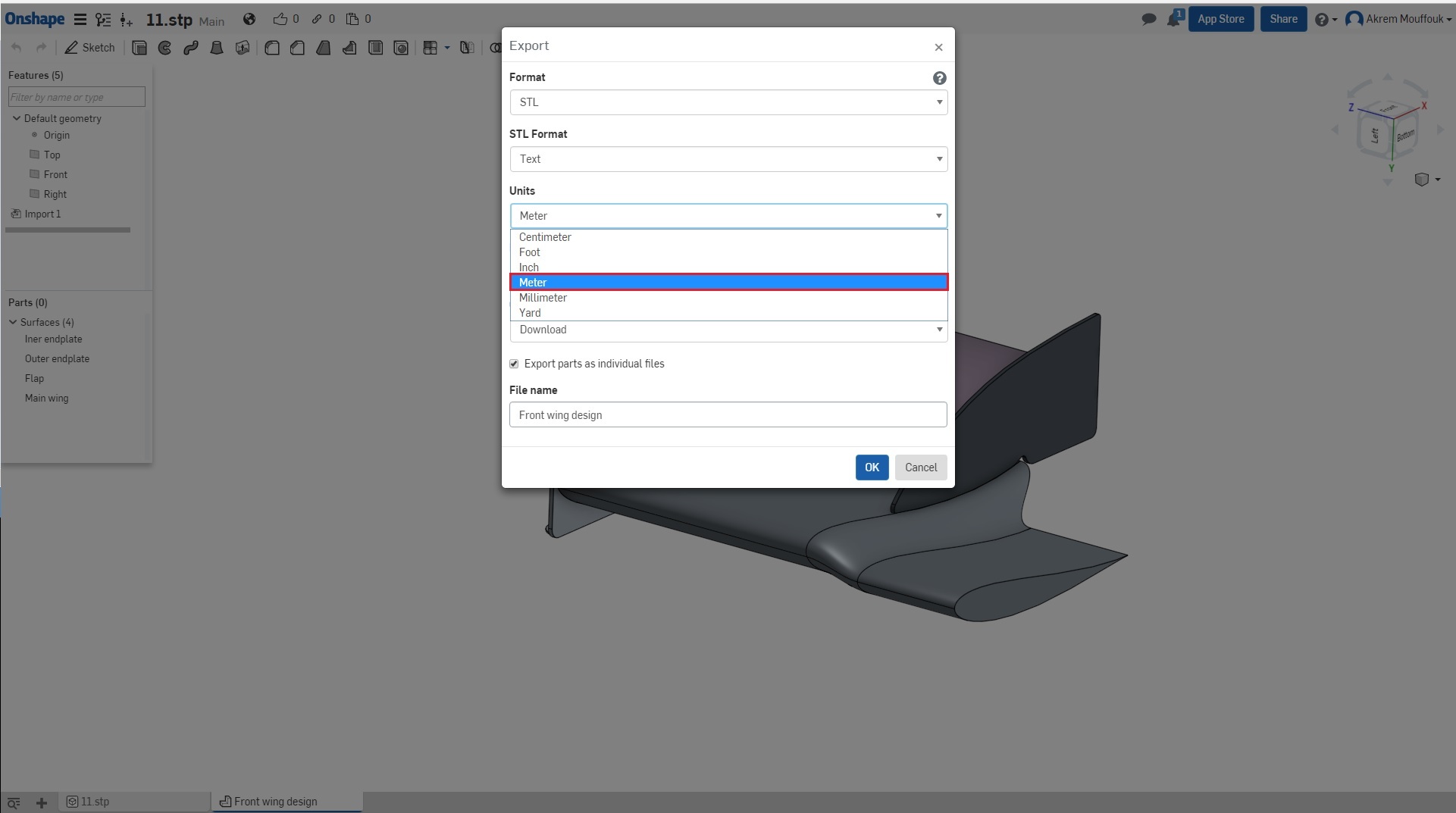
- Please make sure that you have built your model using meter units otherwise scale your model to [m], the unit of SimScale is meter [m].
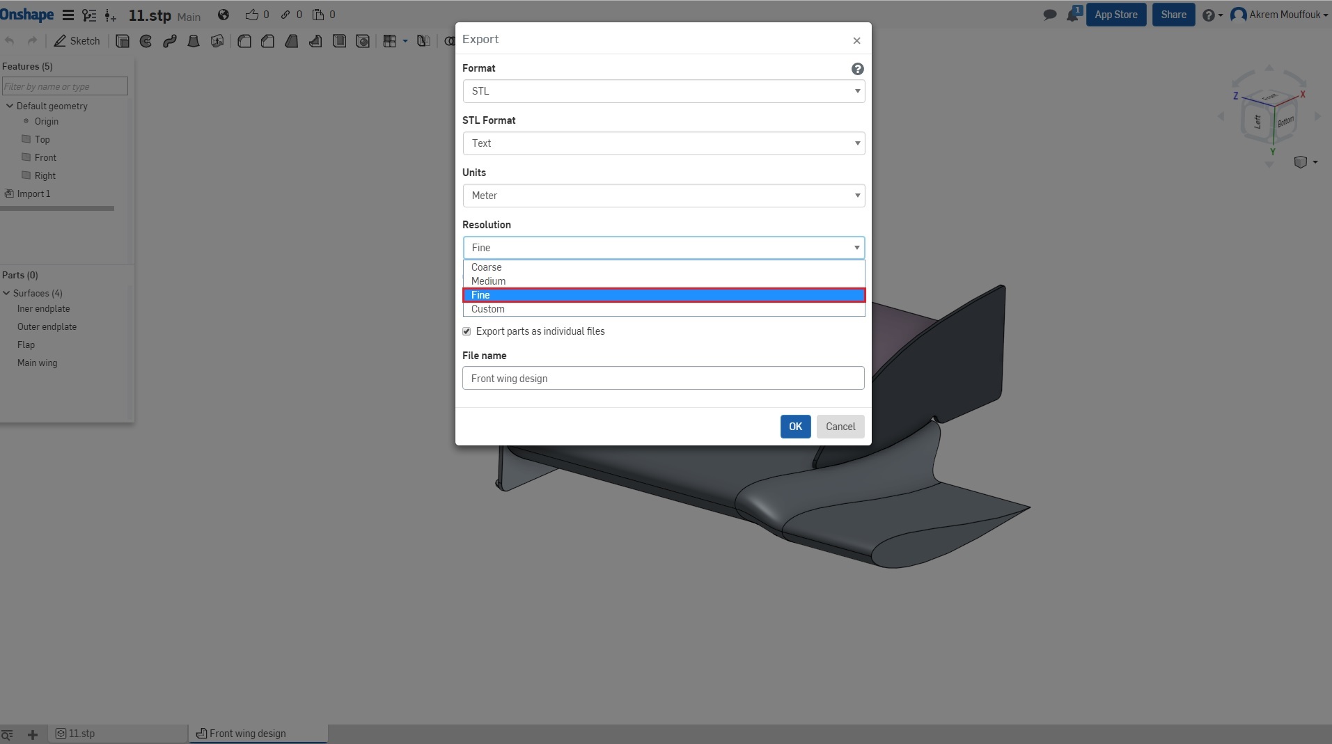
- Adjust your tessellation to good quality using automatic adjustment or customize it.
- If you have this function in your software of exporting STL with multi parts, activate it otherwise follow the above steps.
- Finally name your file and export it.
- In result you will get a file for every part.
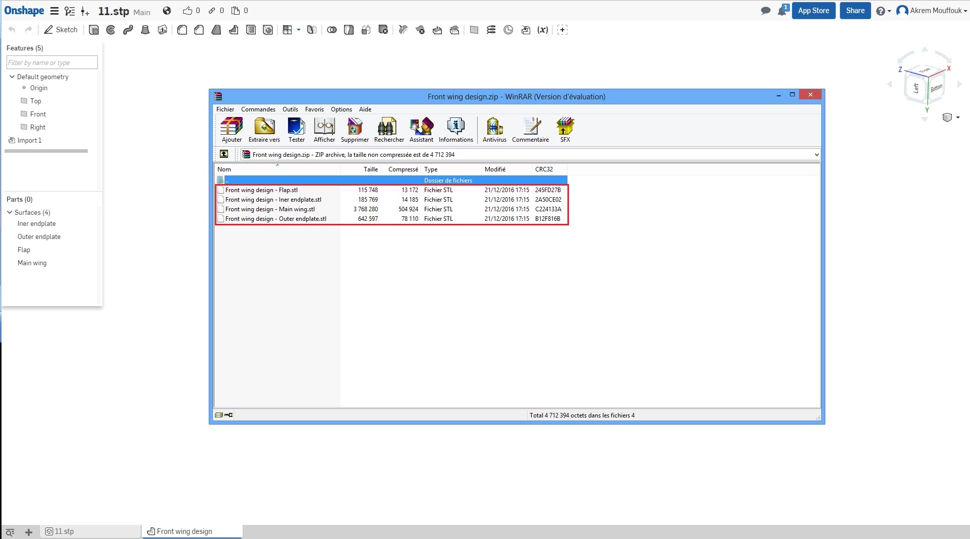
DO NOT use symbols or spaces when naming your STL files. Please just use alphanumeric characters. If it’s absolutely necessary, just use an underscore ( _ )
Make sure you select the correct units (most likely it’s meters) when exporting the STL’s
Merging STL Files
Now that you have all the individual parts for your wing, you need to merge them together and include the car model. We will show you two possibilities to make this happen.
1. Using a script
We will provide you with a script that will do this step automatically for you.
-
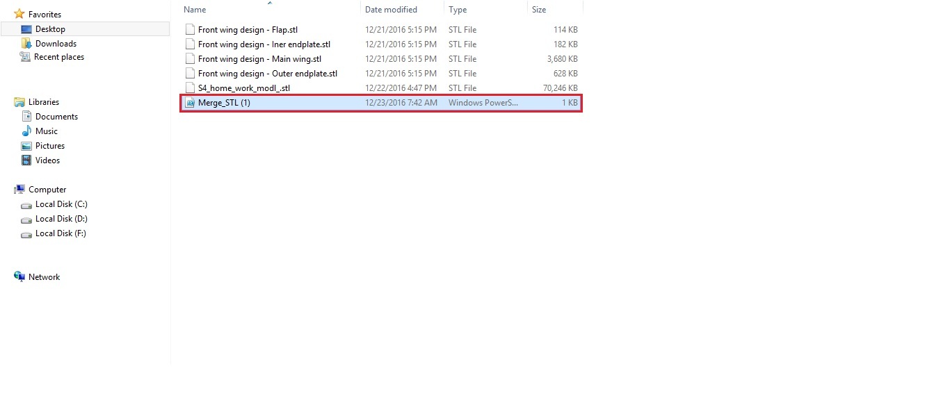
First of all create new folder and name it FSAE 4th session optional.
-
Then put all STL (your front wing design and the car body) files inside the folder which you want to merge.
-
Download the script file from here (Script file download)
-
Now put the script inside the folder FSAE 4th session

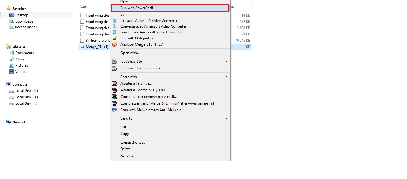
- To merge all the STL files in the same file you have to run the script (right click on file Merge_STL, and run with PowerShell).
- A new window will appear. Click on open.
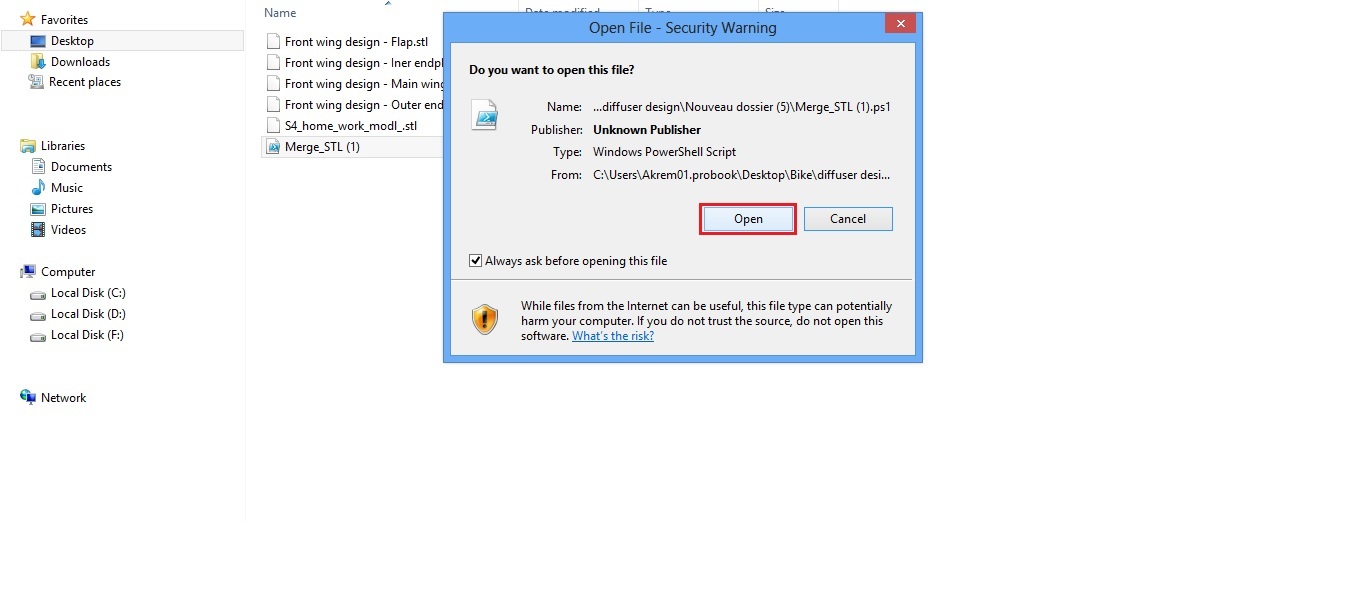
- The merging process can take up to 20 min. After this you will have a new file in the folder FSAE 4th session, containing all the parts together in one file.
2. Using text editor (alternative)
Merging the STL files can be done using another option by editing the STL file itself, to do this you need a text editor. If the script option does not work for you, we suggest this option as an alternative
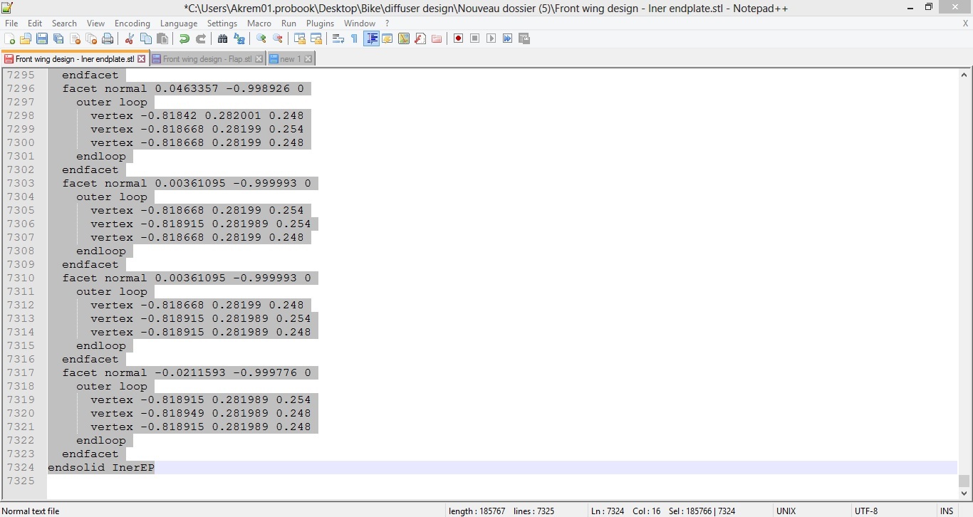
An STL file is essentially a text file with coordinates that define the geometry. In an STL file a geometry begins with a text that says solid NAME where NAME is the name you saved the file with, and it ends with endsolid NAME where again, NAME is the name you saved the file with. Refer to the following picture:
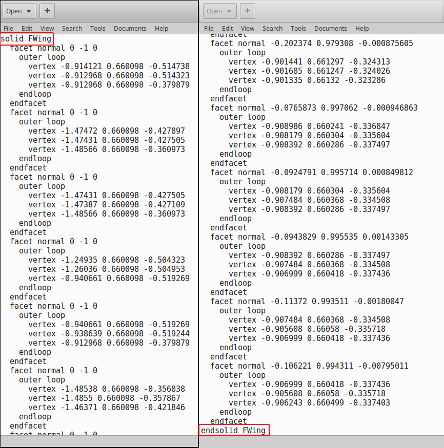
To start merging your STL files first open a new text file and open one of the STL files to be merged. The first step would be copying everything from the STL text to the new text file.
Follow the next steps:
- Right click on the STL file and choose Edit with (your text editor)
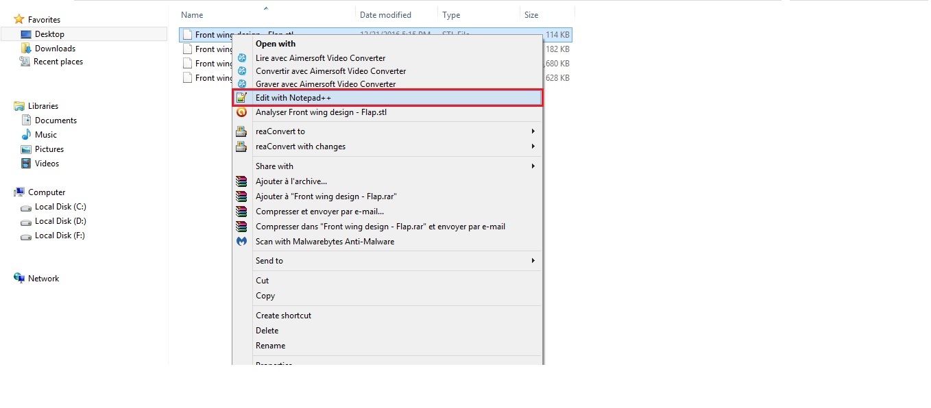
- A new window will open with the text editor.
- Click on the first line solid NAME, scroll down to the end of the text, press Shift and click on the last line in the text, (make sure that you select all the text).
-
Copy the text Ctrl+C and paste it in the the empty text file that you have created using Ctrl+V.
-
Repeat the same steps with the other STL files, but this time you have to paste the STL text after the end of the previous text in the new text file
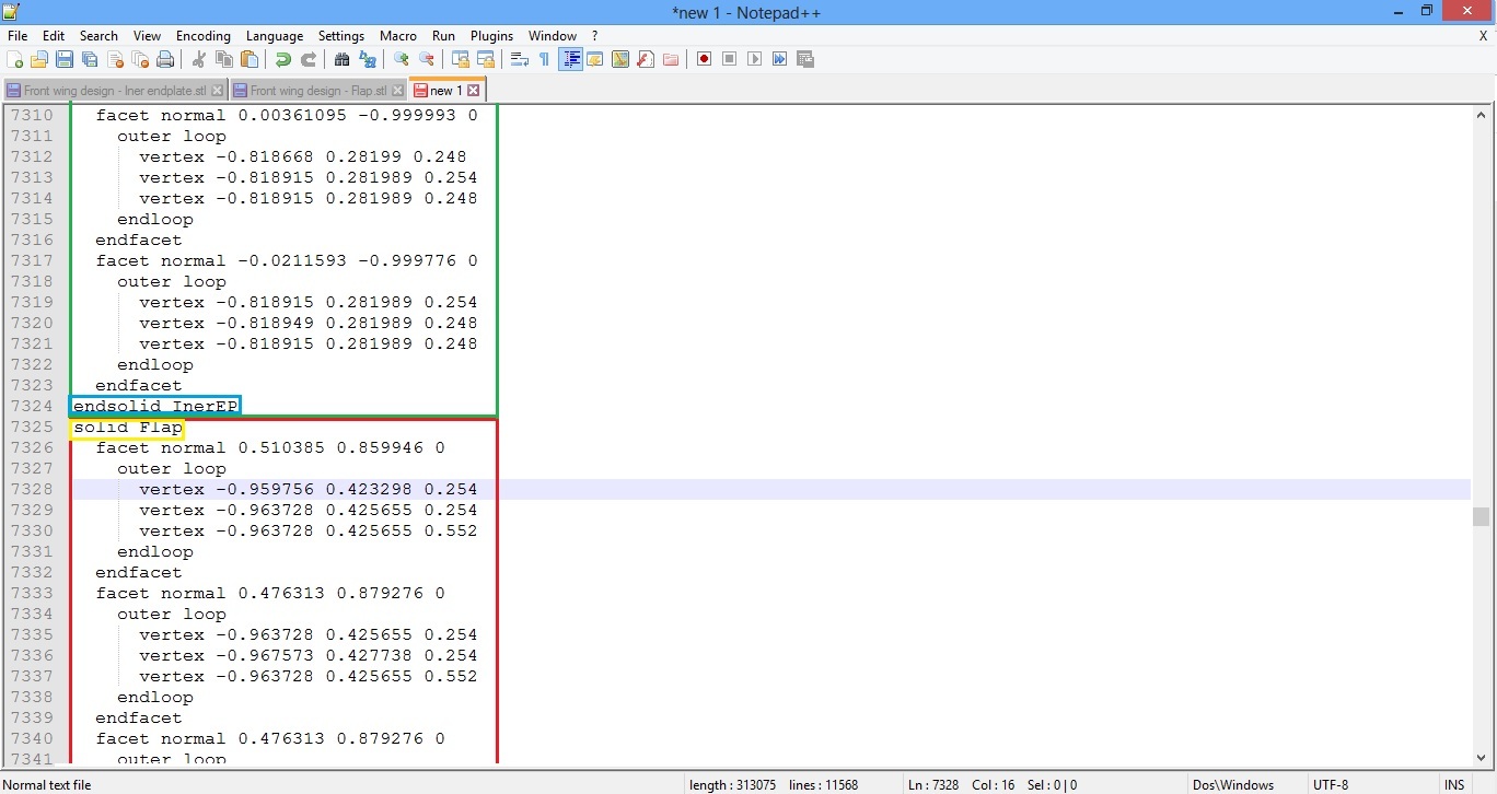
- Do the same steps with all the files of your front wing and car model. You will end up with one file containing all of the car parts.
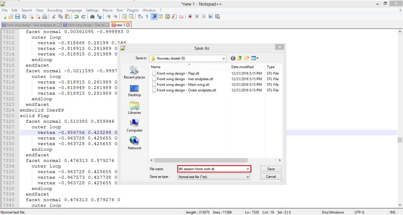
As soon as you finish this step, save the file with the name of the file, but make sure that you add the extension .STL
Creating a SimScale Project
Now that we have the full model with your front wing design and the car body, it’s time to move to the next step, Uploading the new STL to the platform.
To do this go to www.simscale.com and log in.
Then in the Dashboard click on New project in the top right corner.

A new window will appear. Fill the information in with the title of the project, description of the project, category of your project, and you can Drag and drop your CAD files, or select the file from the folder, (select the last file where you have merged all the STL files together).
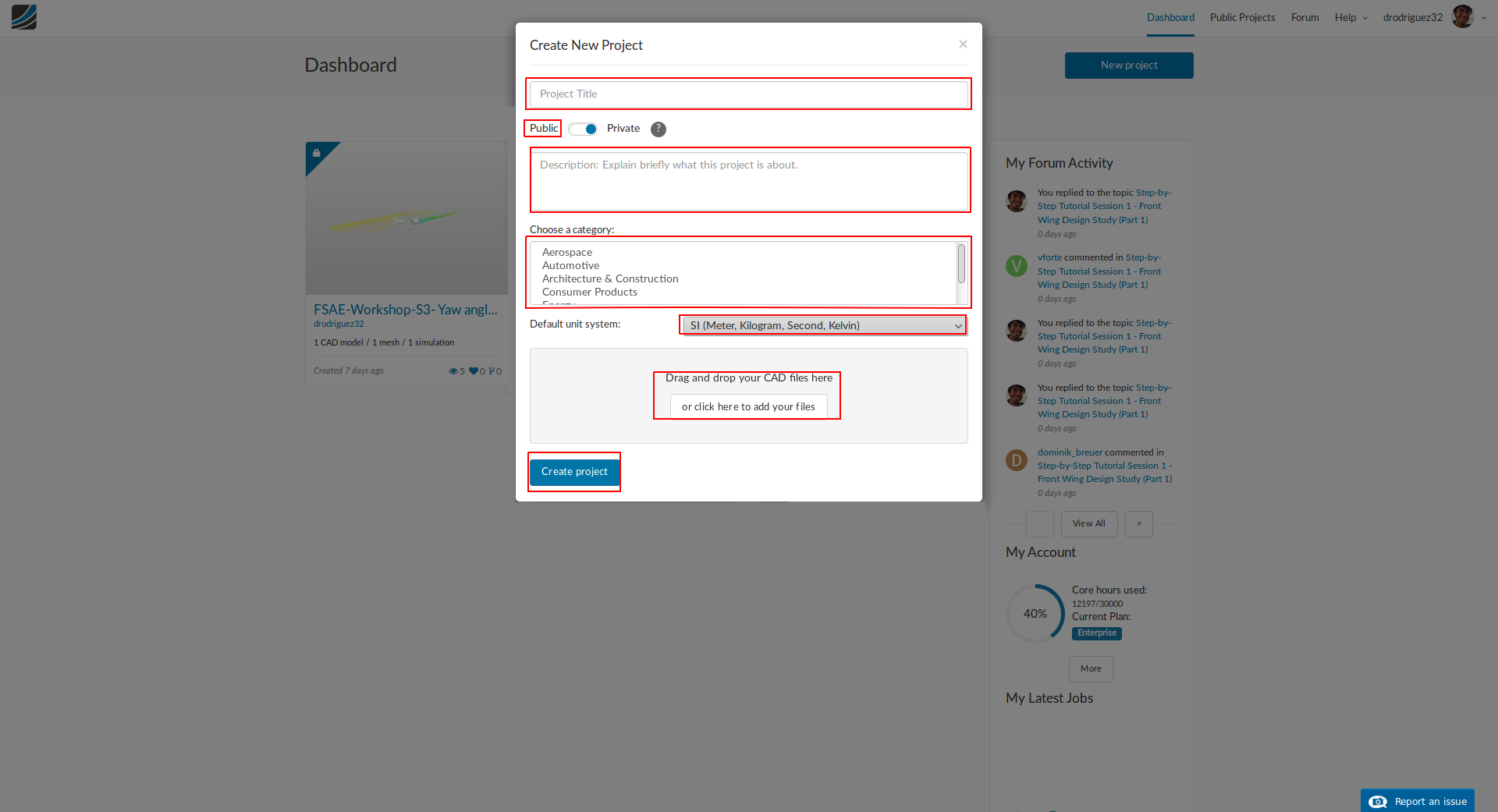
When you finish, click on Create new project, you can proceed with the mesh generation and simulation setup steps describes in the exercise from Session 2.
Common Mistakes/Problems
1. Selecting the incorrect units during export
Most likely you will have to select meters when exporting the STL file to make sure that it will fit with the car model.
- How do you know if you exported with the right units? When you merge the wing with the car, it should fit appropriately.
- How do you know if you exported with the wrong units? When you merge the wing with the car, it will be disproportionately big or small.
2. Selecting the correct STL format
When you export your STL you should select ASCII format. This will create a file that can be merged with the car and imported into SimScale.
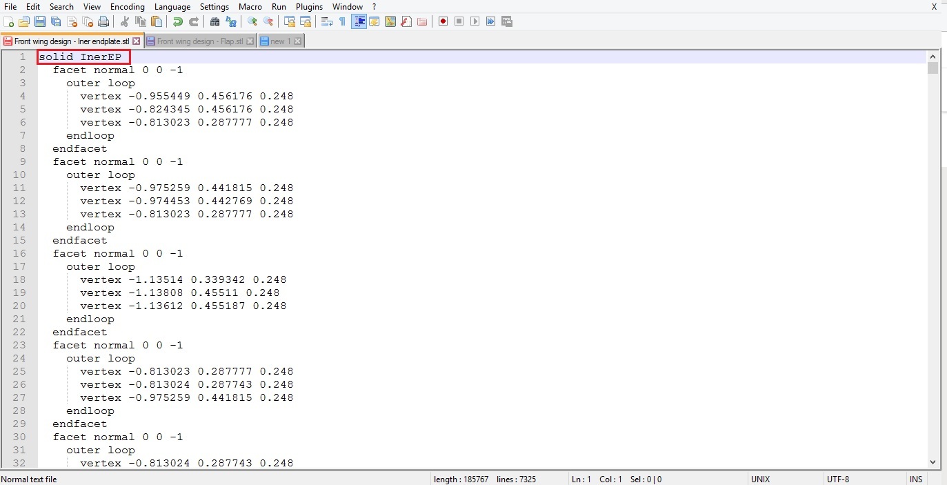
- How do you know if you selected the right format (ASCII)? If you open an STL file with a text editor you will see normal text in Roman Alphabet. And you will be able to merge and upload successfully.
- How do you know if you selected the wrong format (BINARY)? If you open an STL file with a text editor you will see random symbols. And you will not be able to merge and upload successfully.
3. Selecting the correct export quality for STL’s
When you export an STL you should have options to select the quality of the export, and you should always select the highest. If not, you might get an incorrect representation of your design.
4. Wing is out of bounds
When you have your wing design, before you go through the meshing process, make sure that it doesn’t intersect with the nose or the floor or the front wheels.
5. File naming
Never use spaces when naming your STL files, and avoid as much as possible using any symbols. You should stick to letters and numbers. This is just to avoid any silly issues.
6. Exporting all wing parts in the same STL
When you’re generating the solids for your wing, make sure that each component is a new solid, and make sure that you export each component individually.
- How to know if you exported it correctly? You’re going to have to merge multiple files and when you upload it into SimScale you will be able to select each component individually.
- How to know if you exported it incorrectly? When you upload it into SimScale you will only be able to select the whole wing which won’t be good for the meshing or simulation process.
7. Illegal cells/Simulation quit due to numerical instability
After you finish meshing (and remember to mesh only half the car to take advantage of symmetry), go to the Meshing Log and scroll down to the bottom of the text. Look for illegal cells and make sure the number is very small when compared to your mesh (a good recommendation would be for it to be below 0.003%).
Remember that this is not always the case and you might be able to get a a successful simulation with more illegal cells. Equally, you could have a simulation fail with less illegal cells.
If you ran a simulation and it failed due to numerical instability go back to your mesh and check your illegal cells. This is a good way to start troubleshooting.
8. Mesh operation event log
When your meshing is done, under the Mesh Operation Event Log you might get messages like:
- Illegal triangles were found after surface tesselation. There could be a problem with the CAD geometry. Trying to proceed anyway.
- The tesselated surface is not closed. There could be a problem with the CAD geometry (such as self-intersections). Please inspect your geometry. Trying to proceed anyway.
- Mesh quality check failed. Mesh is not okay
Please don’t be alarmed. Inspect your mesh, do the surfaces look good? Do you have few illegal cells? You most probably can go ahead with the simulation setup with no problem.
You should have, ideally, below 10 million cells. The model for Session 2 had 8.3 million cells.
CAD Tool Specific Videos
We know that the process of this tutorial can vary greatly between CAD tools. In the video(s) below, you will find an example of how to export your own front wing design using Autodesk Inventor. Of course, this is not the only CAD tool you can use: SolidWorks, CATIA, Siemens NX and the list goes on.
Autodesk Inventor

Solid Works
(Looking for a volunteer…)
Do you use SolidWorks? Create a short screen recording of how to edit and export the front wing and car as an STL and share it in the comments section. I’m sure your fellow workshop participants will thank you ![]()
CATIA
(Looking for a volunteer…)
Do you use CATIA? Create a short screen recording of how to edit and export the front wing and car as an STL and share it in the comments section. I’m sure your fellow workshop participants will thank you ![]()
Siemens NX
(Looking for a volunteer…)
Do you use CATIA? Create a short screen recording of how to edit and export the front wing and car as an STL and share it in the comments section. I’m sure your fellow workshop participants will thank you ![]()
Recommendations About Comments
Before you comment:
- Make sure that you have thoroughly gone through the tutorial, especially the Common Mistakes/Problems section.
- Check the comments to see if someone has had a similar problem and it has been solved.
 We will get this done together no worries!
 Will think about another solution too. Let me know if you managed to fix the issue by yourself in the meantime.