Hi Simscalers of the world!
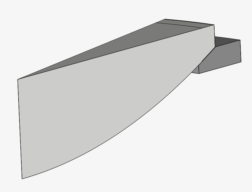
I am facing some problems importing to SIMSCALE a mesh created in SALOME 9.5.0. According to the instructions given in the Documentation, only MED meshes can be imported, so that is the format I use when exporting from SALOME. I have tried versions 3.2 and 3.3 without any success. I have to say that this is the first time I work with SALOME, so I am also facing some issues when creating the meshes themselves. However, when I get a mesh properly generated I am not able to import it to SIMSCALE. The geometry can be seen below.
It is a multibody simulation to study the hertzian stresses between both solids, which makes the mesh creation process a little bit trickier… Here you can find the simulation. I have already done some simulations meshing within Simscale but I want to try a more structured mesh to compare, that’s why I am trying to create the mesh externally. In order to do so, I tried some ways to do it with SALOME that I will try to explain now. The procedures I tried are the following:
-
Starting from the multibody STEP in the Shaper. Defining the groups of faces and bodies so as to be able to define the boundary conditions in Simscale. Creating 1 mesh per body independently and exporting both meshes in a MED file.
-
Starting from the multibody STEP in the Shaper. Defining the groups of faces and bodies so as to be able to define the boundary conditions in Simscale. Meshing the multibody in a single mesh and exporting it in a MED file.
-
Starting from the multibody STEP in the Shaper. Defining the groups of faces and bodies so as to be able to define the boundary conditions in Simscale. Creating 1 mesh per body independently. Creating a compound mesh with the two meshes and exporting it in a MED file.
-
Starting from two STEP files, one per body, in the Shaper. Defining the groups of faces and bodies so as to be able to define the boundary conditions in Simscale. Creating 1 mesh per body independently. Creating a compound mesh with the two meshes and exporting it in a MED file.
-
Starting from two STEP files, one per body, in the Shaper. Defining the groups of faces and bodies so as to be able to define the boundary conditions in Simscale. Creating 1 mesh per body independently and exporting both meshes in a MED file.
None of the above procedures have given a a good result, only error messages when imported to Simscale. Errors like “The imported MED mesh contains a face that is not attached to any region", "internal-error” and maybe some other that now I can’t remember.
I also tried to import single body meshes with the same level of success…
Is there any problem in importing externally generated meshes? Or am I doing something wrong?
Please, any tip or suggestion will be much appreciated since I don’t know what to try next. In case you need more information regarding my simulation, do not hesitate to ask!
Thanks in advance.
Best,
Alex
Hi Alex,
Importing MED meshes is a little tricky, even I get some errors when I try it. The best recommendation would be to stick to the Standard meshing algorithm for best results.
That being said, I think you need to create mesh groups for each entity that will be used for simulation, including:
- Volume groups for each one of the parts
- For each part, face groups for each individual face
Good luck!
1 Like
Hi @ggiraldof ,
Thanks for taking the time to respond that quick! 
It doesn’t sound nice when someone like you also have problems…
This is really interesting! Let me ask you something regarding this. Does ALL the faces need to be grouped? Or only the ones that will be used as BC? As per the documentation I undesrtood that only the ones that will be used as BC… Maybe the errors come from a bad grouping… Does Simscale detect automatically the bodies or faces groups and if some body or face is not grouped it shows up an error?
Something interesting to try tomorrow…
Again, thanks a lot! Any other tip will be much appreciated
Best,
Alex
2 Likes
One group for each face, that is what has worked in the past for me. Obviously the minimum would be only the ones you will use for BCs, but I got better results when done for everyone.
2 Likes
Hi @ggiraldof ,
Thanks for your insights again. After a long, long, long… strugge I have managed to upload a mesh. An interesting point I learnt is that the names given to the groups of bodies and faces MUST NOT contain spaces otherwise the simulation crashes before starting to simulate. I leave the information here since it can be useful for anyone else in the future (even for myself, actually…).
Now I have another problem… The solver stops giving this error message:
The solution matrix is singular. This may be caused by an unconstrained rigid body motion, a physical contact definition with open gap in a nonlinear static analysis or incoherent material parameters.
I bet that the second cause pointed out in the message is the one that is causing the crash, but I don’t know how should I proceed to solve it. Besides, looking into the log I found a message that I don’t really understand and may be of interest.
   !-----------------------------------------------------------------------------------------------------------------------------------!
   ! <A> <COMPOR2_23>                                                                                                                  !
   !                                                                                                                                   !
   !    Il y a incohérence entre le champ des variables internes et le comportement affecté sur les mailles (si vous ne l'avez pas     !
   ! précisé, on suppose par défaut                                                                                                    !
   ! que le comportement est élastique).                                                                                               !
   !    On ne peut pas modifier le champ des variables internes de manière automatique.                                                !
   !    Mais comme vous semblez être dans un cas autorisé (voir message précédent), la reprise de ce champ dans un calcul non-linéaire !
   ! devrait bien se passer (correction automatique dans l'opérateur).                                                                 !
   !                                                                                                                                   !
   !                                                                                                                                   !
   ! This is a warning. If you do not understand the meaning of this                                                                   !
   !  warning, you can obtain unexpected results!                                                                                      !
   !-----------------------------------------------------------------------------------------------------------------------------------!
I leave the link to the project here, just in case anyone can give me a hand with that.
Thanks in advance!
Best,
Alex
3 Likes
Hey @alex_roque
I think the singular matrix is caused by shared slave nodes between the cyclic symmetry and the physical contact. Please fix this by modifying the geometry, and avoid shared edges between the concepts.
3 Likes
Wow! That makes sense. Thank you again! I will try what you suggest right now!
2 Likes
Hi,
Finally I got the simulation running with an uploaded mesh!  Most of my problems came out due to a very tiny feature that was created in the CAD design which led to some tets with an extremely high aspect ratio (over 200 and sometines even 1000). After cleaning the CAD the mesh came out with very nice aspect ratios (below 4). The mesh importation process worked without any trouble and the simulation run smoothly with very nice results!
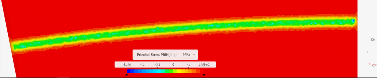
I think that in this case, where I wanted to compute the contact stresses between an aspherical glass lens and a conical metal surface, the use of a structured mesh in the contact interfaces is justified since using the unstructured meshes given by the standard mesher yields an irregular contact area with some points overstressed. This is not what should be expected according to the Hertz theory, considering this is a case of cylindrical contact with a line of contact.
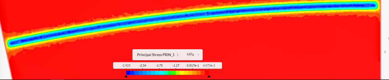
Below some results are presented of the 1st principal stress in the lens. Both have the same load applied (-55N in a 12º wedge simplified geometry). Penalty method is used with a Penalty Coefficient of 1e13.
Unstructured mesh
Structured mesh
The results expected according to Hertz contact theory, however, were a 1st principal stress of 5.62 MPa instead of 2.9 MPa. I tried changing the value of the Penalty Coefficient and it has a massive effect on the results! A value of 1e14 yields a principal stress of 5.67 MPa (the expected value according to the Hertz formulation) and a value of 5e14 gives a principal stress of 8.59 MPa…
This disparity makes me wonder what value for the Penalty Coefficient should be used and if theare is a way of estimating the proper value. I know that the documentation gives us a starting point of 5-50 times the Young Modulus, but I would like to know something more accurate…
Besides, I don’t know if the issue with the principal stress vectors comented here has any effect on the results. I hope it gets solved as soon as possible…
Again, @ggiraldof thanks for your support!
Best,
Alex
1 Like