I have 2 doubts regarding principal stress directions in post-processing evaluation:
I don’t understand why the magnitude of the vector given by the 3 component
VECT_1_X, VECT_1_Y , VECT_1_Z seems to be not equal to one
and
-the vectors seem to be not orthogonal, ie the scalar product is not equal to zero
here is an example
Points:0
Points:1
Points:2
Principal stress:0
Principal stress:1
Principal stress:2
Principal stress:3
Principal stress:4
Principal stress:5
Principal stress:6
Principal stress:7
Principal stress:8
Principal stress:9
Principal stress:10
Principal stress:11
-0.04619
-0.1972
-0.0015713
-1.24E+05
-12731
1.57E+05
0.115
-0.085874
-0.13017
0.95672
0.21066
0.15838
-0.0020531
0.30154
-0.20803
I suppose
VECT_1_X, is Principal stress:3…VECT_3_Z is Principal stress:11
from this example results are:
Vect 1 ,2, 3 magnitude: 0.193761639 0.992358311 0.366342828
scalar products xy,xz,yz 0.214192475 0.242509159 0.028610383
what is it wrong?
I am working on a python script for paraview in order to calculate the principal stress vectorial difference for fatigue following the method of principal stress difference
Thanks for reporting this bug, I have been facing exactly the same problem in my last simulations for some days and now I am doubting on the validity of the results since the non-orthogonality of the principal stress vectors. Did you find any solution?
In my case I created the vector fields for the principal stress vectors in paraview just to check if they were orthogonal, as they should, and although many of them seem to be orthogonal (I didn’t check it with the dot products) many of them are visually completely non-orthogonal.
In my case, when I export the results to a CSV from paraview the vector coordinates I get are even more messy as it can be seen in the table below. The first two values are the principal stresses along with the Principal stress_2, but in between two more columns are found…
Principal stress_0
Principal stress_1
Principal stress_10
Principal stress_11
Principal stress_2
Principal stress_3
Principal stress_4
Principal stress_5
Principal stress_6
Principal stress_7
Principal stress_8
Principal stress_9
-2255680
-1196040
-0,0154126
0,308762
-687783
0,099797
0,206791
0,370522
0,216537
0,622758
0,196603
0,729076
It looks even more ridiculous when seen in Paraview. All columns are named with the same name and the second and third columns are kind of joined together in only one column.
Why principal vectors are not normalized? Why are they not orthogonal?
Hi @ggiraldof and the rest of the staff involved in this issue,
I have been researching a little bit about my case that can be found here and some information regarding itself can be found in this other topic.
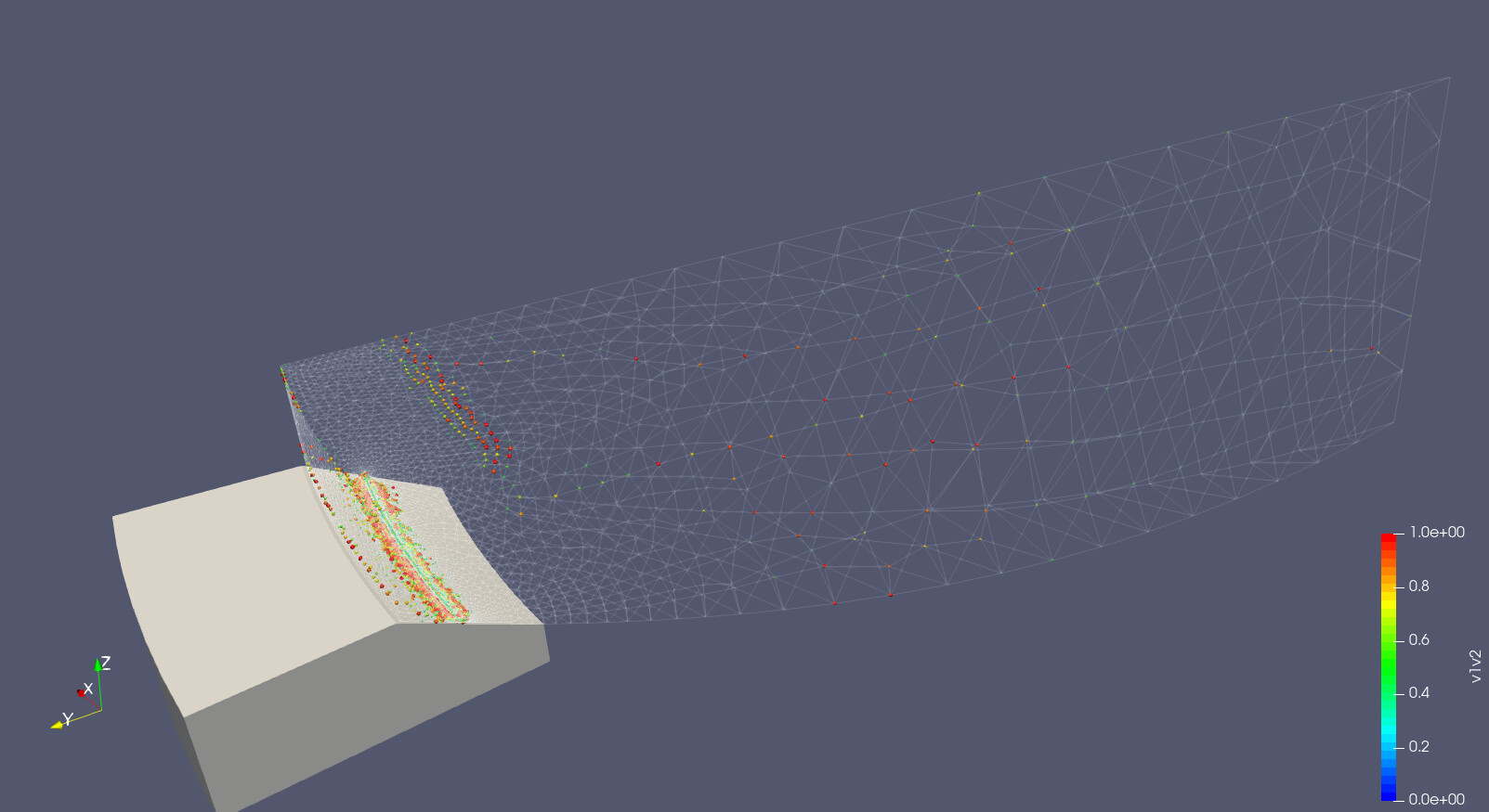
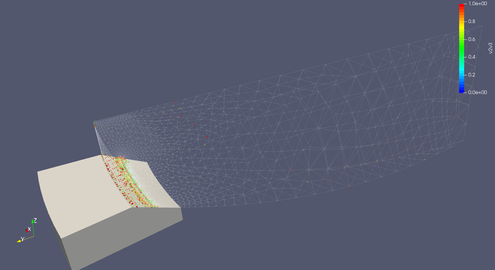
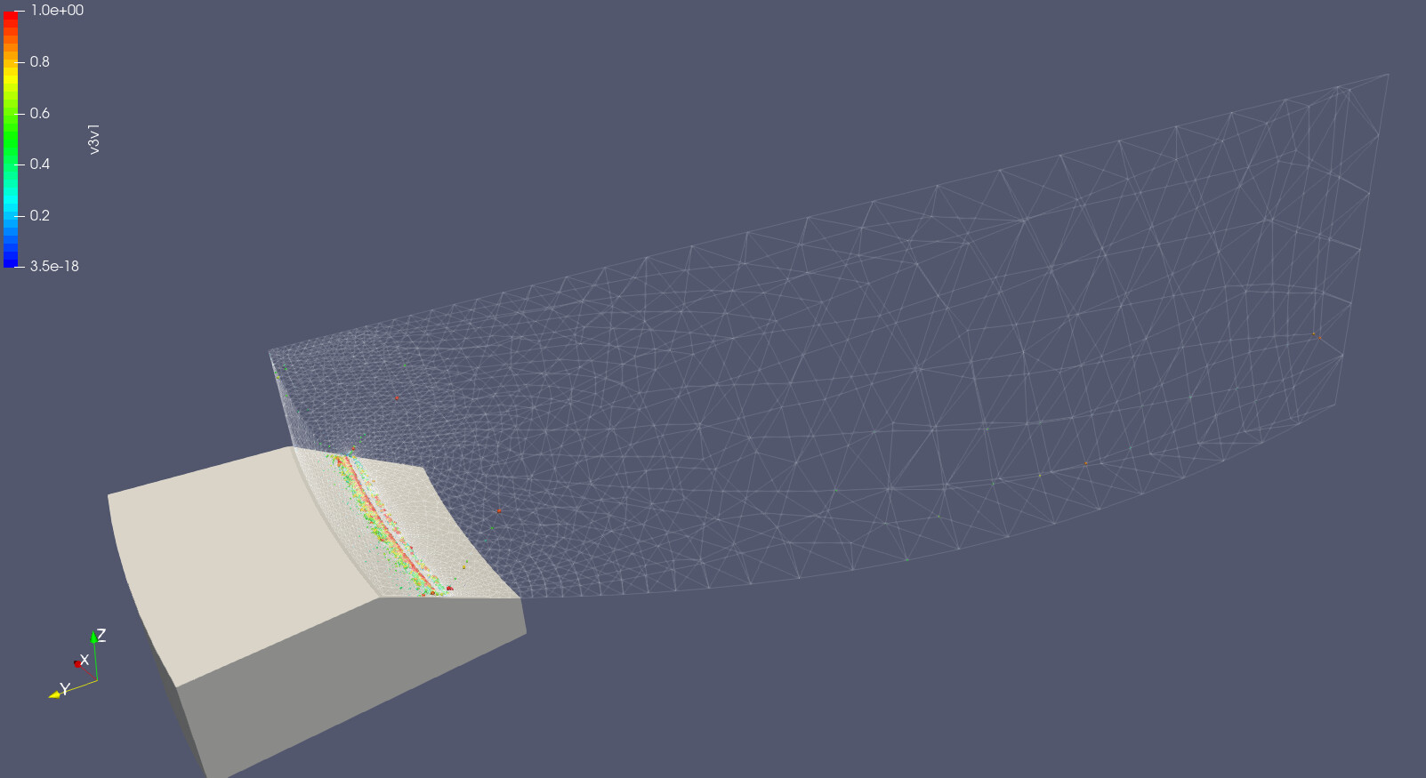
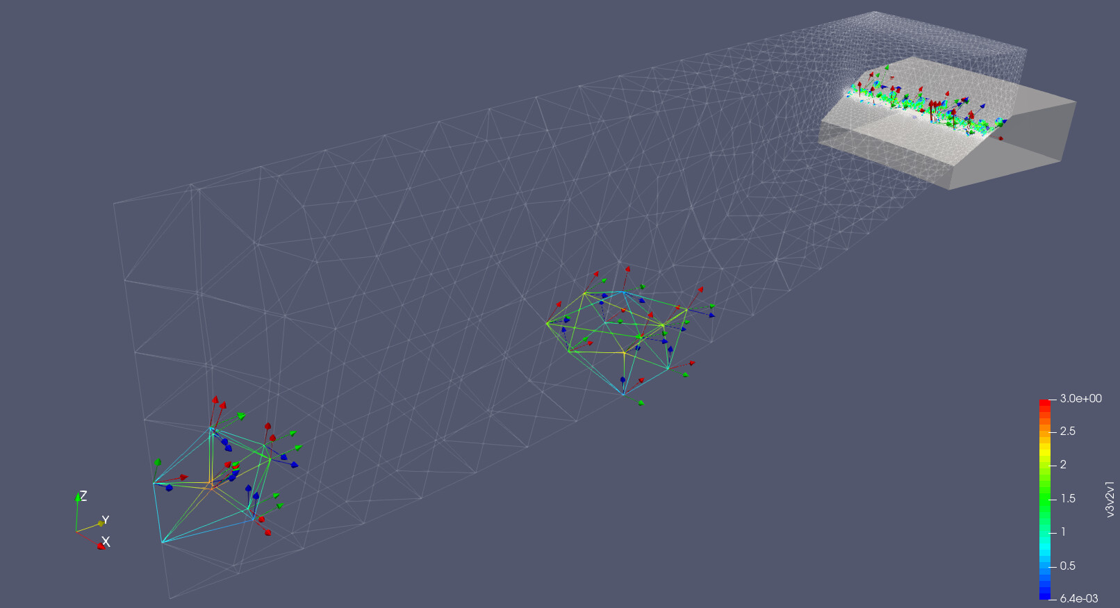
I have represented the absolute value of the dot products of the principal vectors in paraview so as to find the points where orthogonality is not reached. Representation is by means of spherical 3D Glyphs , scaled by module, so the bigger (and redder) the spheres are the further we are from orthogonality. Below some screenshots are presented.
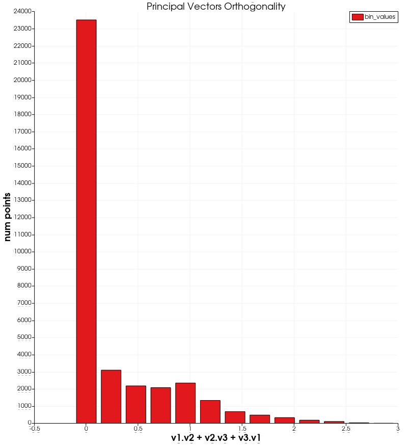
Furthermore, I summed all the results and got surprised to see that some points had a value close to 3, which means that all 3 principal vectors are close to be parallel. Something completelly unexpected…
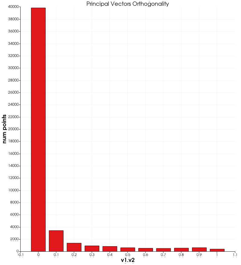
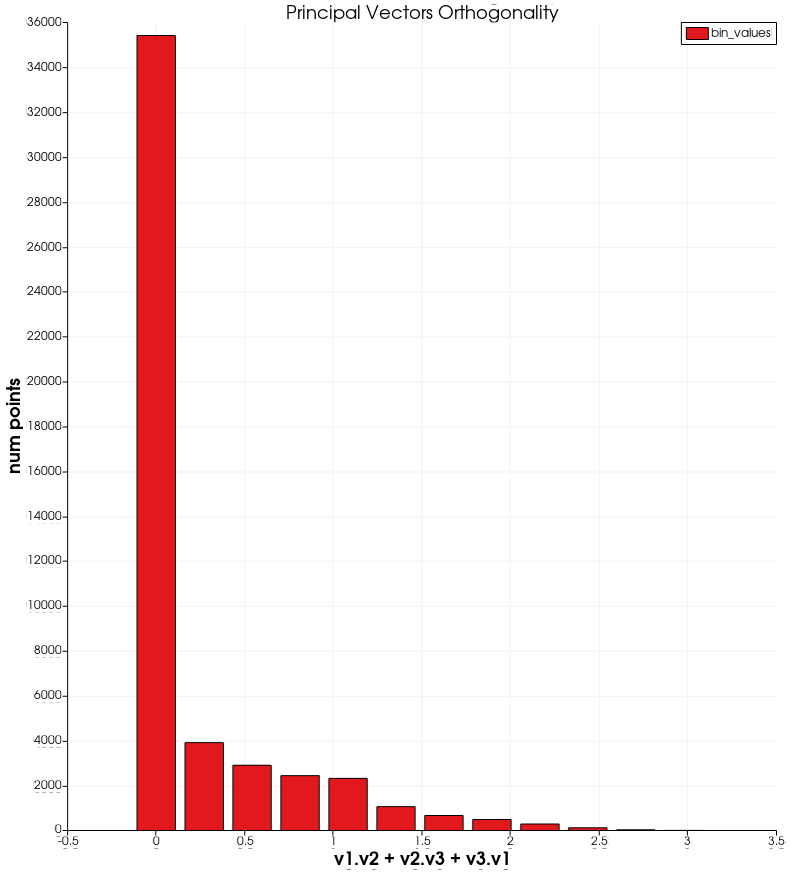
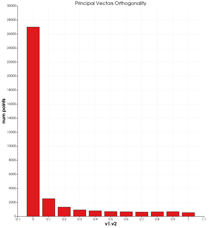
I also investigated the histograms of the dot product values since in the previous images only the boundary values were represented. Only the histogram for v1·v2 is shown since the other two look very similar.
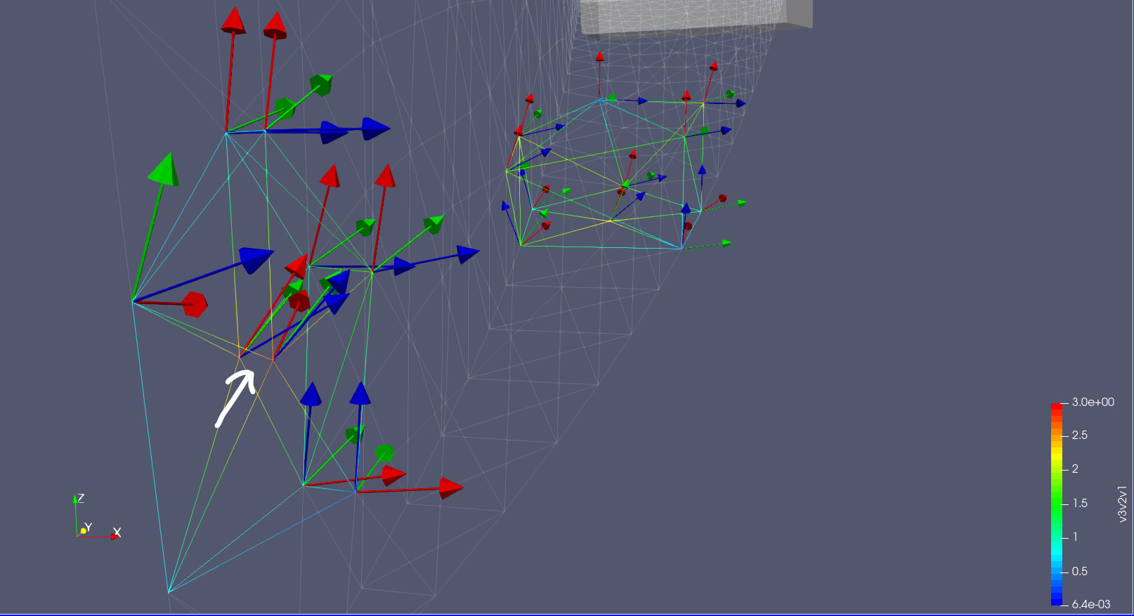
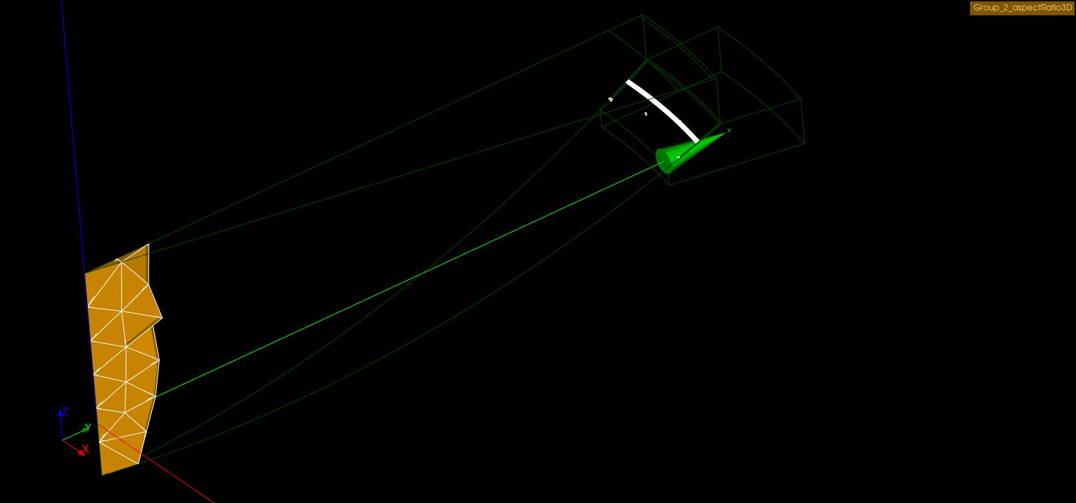
Finally, as a crosscheck, I extracted the tetrahedrons containing values greater that 2.25 of the sum of the 3 dot products and represented the principal vectors as glyphs. Tets are colored with the sum of the dot products so as to ease the search for the most critical points.
I hope that the information shared here can be helpful to illustrate the problem and to find a solution to it. If I can do something to help, just let me know.
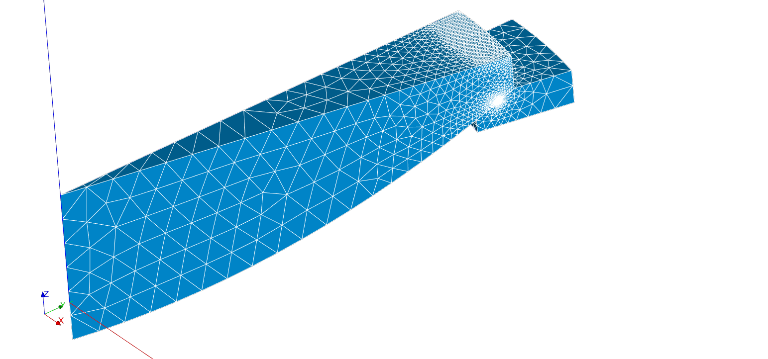
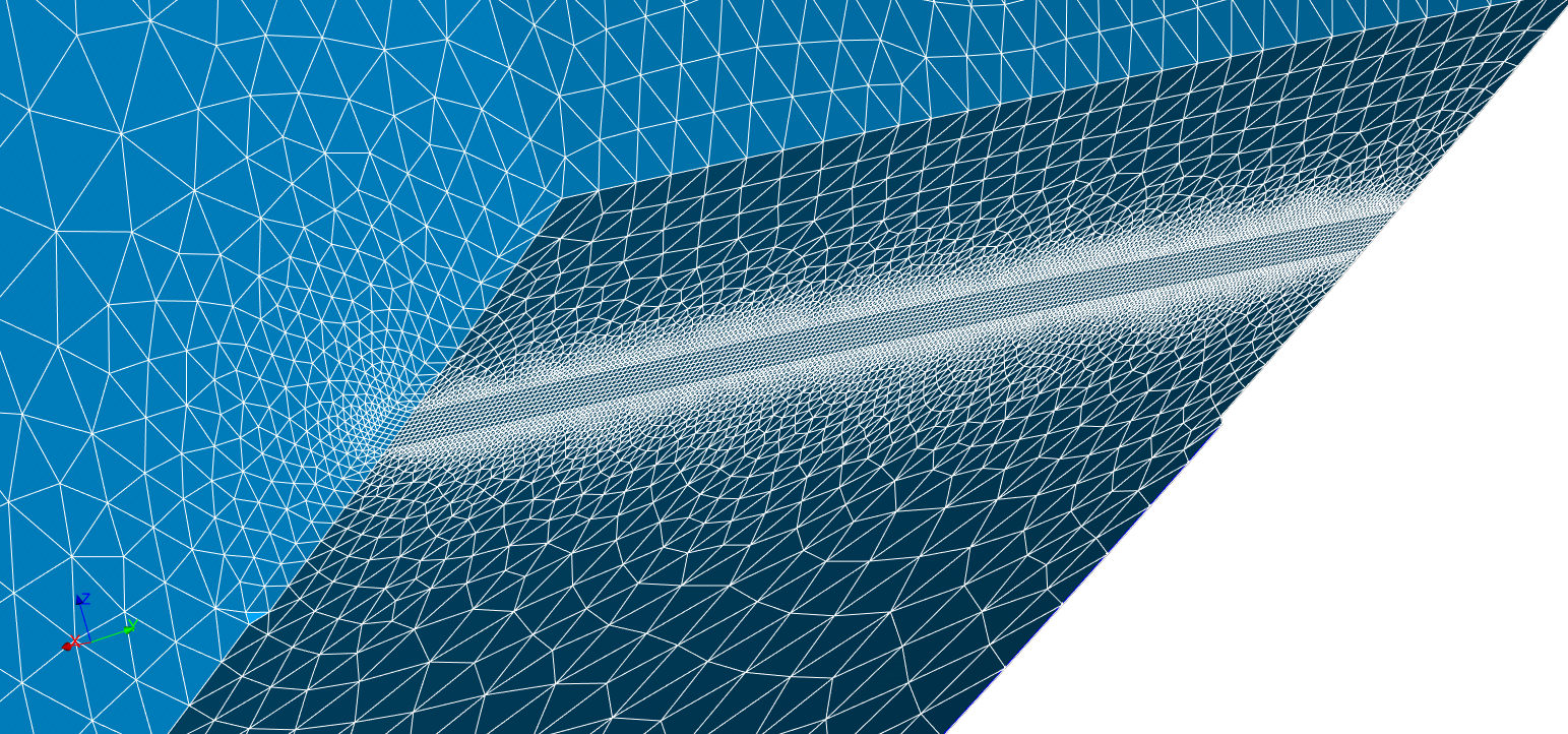
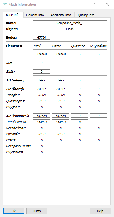
Thanks for asking. No, I haven’t and it could be a good starting point but, first, let me give you some information regarding the mesh. The mesh has been created in Salome and imported to Simscale, not without problems, as it is stated in this other thread. The mesh is made of tets, except for the region of contact between both solids, where I defined the interface to be made of squares to make it even more structured. Actually, both parts of the interface have been meshed with the same parameters so that the contact interface is “quasi-conformal” (if this word exists… ). This point is important as I mention in the other thread which link I already posted above. This gives an interface made up of pyramids instead of tets, not sure if it can be causing the problem (or part of it), but investigating the mesh I found something interesting regarding the pyramids that I will mention later.
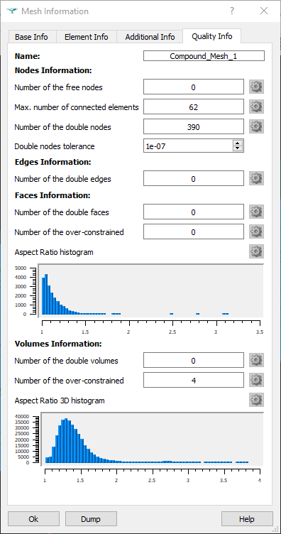
Now let’s go to see the mesh in detail. Below some pictures will tell you more about the mesh than I can write!
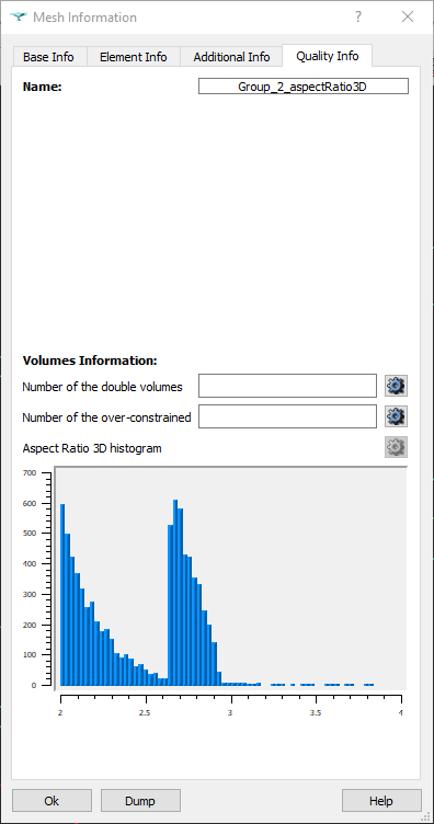
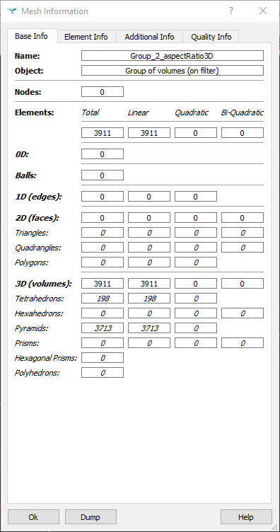
I think the histogram says that the mesh is of reasonable quality. However, to have a closer look into it I grouped all the volumes with an Aspect Ratio 3D greater than 2 and the histogram of it looks quite interesting… Let’s see it!
Only ALL the pyramids and some degenerated tets are showing up and it makes me wonder if 2.64 is the lower bound for the aspect ratio of a pyramid, is it?
Now that you know better my mesh, what changes to the mesh you recomend me in order to perform the mesh sensitivity analysis?
Just to give you more information, in a previous simulation with exactly the same geometry but meshed in the standard mesher (unstructured mesh, especially in the contact interface) I got non-orthogonal principal vectors aswell. Right now I am analyzing the previous simulation in the same manner I did with the mesh built in Salome, but, so far it seems that the location of the non-orthogonal principal vectors is alike. I will give you more information once I finish the analysis.
The locations of the non-orthogonal principal vectors follow the same pattern: the most of them are near (or at) the contact surfaces and some in the lens body in degenerated tets. The mesh can be found here (Mesh 2_v11).
Hey Alex, and thanks again for the detailed analysis, good stuff.
I think that you should perform a mesh refinement analysis, by refining the mesh around the areas with the non orthogonal principal vectors, and checking the orthogonality again. This is to know if this has an impact.
Please perform such study and let me know of the results.
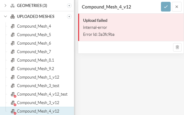
I have been trying to recompute the refined mesh in Salome following the same steps I did previously but now it doesn’t allow me to import it. It gives an “internar error” message when importing…