i have taken a look at many MRF setups and think I have set it up just like them… Been alt+tab through them and my setup and can’t spot the difference.
The reason why it’s only 25s is because I am trying to see if the MRF spins early on since I am getting divergence later on. And trying to save my hours.
When you mention that you want to check whether the MRF spins early on or not I have the impression that you might be misinterpreting what the MRF actually does. It will not spin. The mesh will not move at all; that’s why it is a steady-state approach that simulates rotation by adding a source term (acceleration) to the momentum equations.
Having said so, I would suggest ramping up the angular speed of the propeller. You could start with a low angular speed for a few hundred iterations and the add increments to that speed till you get your desired 575 rad/s. Maybe even start with no angular velocity in order to discard any other issue with the mesh.
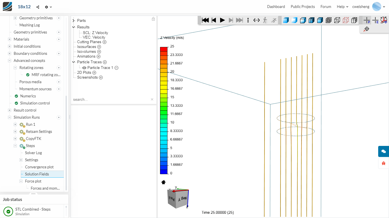
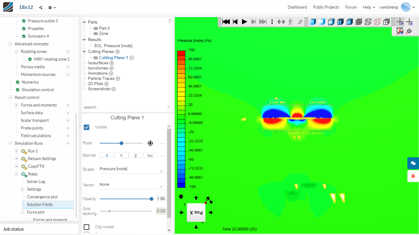
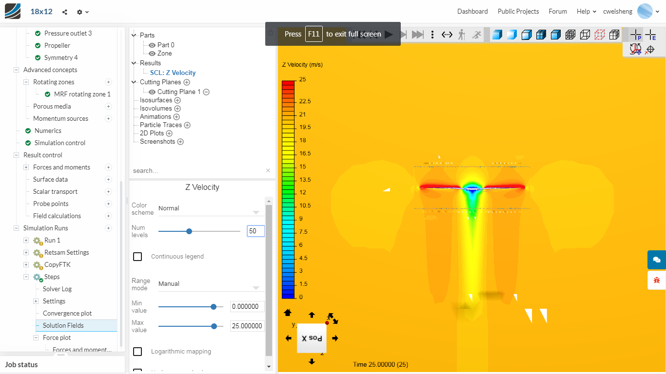
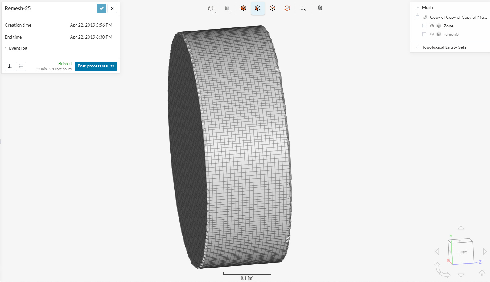
In the images you can see some discontinuity between the MRF zone and the rest of the volume.
Also, if you have a look at the Zone mesh, you’ll see that the edges have not been properly captured. Add a feature refinement, in order to better capture the edges of the cylinder.
@DaleKramer asks good question: set BMB walls to slippy walls (except inlet and outlet). Moreover, in ‘Materials’ you need to specify as ‘Air’ only ‘region0’. When you decided to use full resolution for propeller?
I think I missed something, why are your BMB tunnel walls listed as symmetry boundary conditions, what about slip walls on BMB tunnel?
→ I used to do them as symmetry (another software) and the results were ok. I can set them to slip walls I guess.
Moreover, in ‘Materials’ you need to specify as ‘Air’ only ‘region0’. When you decided to use full resolution for propeller?
→ I have done both for ‘Materials’ whether it is just region0 or both. Same outcome.
→ Full resolution because the y+ is down to 1. I believe I tried wall function and it is same outcome.
Well, I did not discovered that use of symmetry wall, as documentation of SymScale states:
The symmetry boundary condition defines a mirror face/surface. The symmetry condition should only be used if the physical object or geometry and the expected flow field pattern of the developed solution is mirrored along that surface. This boundary condition helps to reduces the computational domain in size and enables the modeling of a sub-domain of the complete setup.
This is good answer, but if you had not a working MRF setup before (tested on coarse mesh), it is more tedious to debug the setup.
The first idea is would not fly. Lower or higher rpm is not the culprit.
You symmetry boundary without the role of being a symmetry still puzzles me, but I cannot tell if those boundaries will work as ‘zero gradients’ wall or ‘no-slip’ wall.
Did you ever have a successful MRF setup with that project before, please?
One more thing, @cweisheng. In order to short you simulation time, I suggest following setup, until culprit is found:
Set Inlet flow to 0, no wind from front, for the moment.
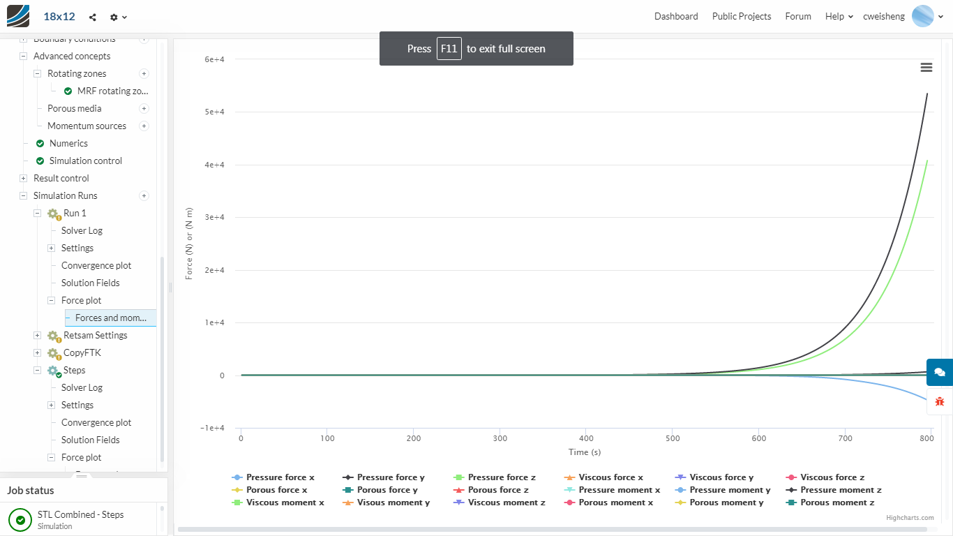
In ‘Result control’ > ‘Surface data’ use your Outlet wall to gather the Forces
Set simulation to ~ 50 steps.
Now, when MRF starts to work, you will notice very soon the pressure, velocity, k, etc. on Surface data plot. If nothing happens, break it, just set another run, modifying one parameter at time.
Actually I have been very successful in the other software - not just MRF but actual rotating propeller on unsteady flow, and even with close-by aircraft fuselage. We validated the trends with wind tunnel data as well, be it for propeller alone or propeller with body. Which is why I’m struggling to find out how I can even begin to have a successful sim in SimScale…
Its at the bottom of the box as per above picture.
Can I check where should the material point be? Inside the MRF cylinder or outside?
And I generated the mesh with it being INSIDE the MRF. If now I need to move it outside the MRF, do I need to remesh?
 )
)