Boundary Layer Does Not Form - Except When Default Settings Used

Hi,

Was advised by @jousefm to start a new post.

I am testing out simulation on propeller aerodynamics. Have previously worked on these in STARCCM+. Ideally, would like to model down to Y+<1 but so far, just shooting for y+>30 for a start since I am still experimenting with SimScale.

The project is here: SimScale

Would like to generate a mesh with the following settings:

  • Expansion Ratio 1.3
  • 10 layers
  • Final layer thickness 3.61e-3 m
  • First layer thickness 3.4e-4 m

If I set the boundary layer finer than the default settings in “Inflate Boundary Layer”, it doesn’t form.

Please advise how it can be resolved.

Thanks.

Weisheng

Hi @cweisheng,

The following resource should help you.

Do take note that the mesher is very sensitive to the geometry, so ensure that it is of highest quality and good CAD practices are maintained.

Also aim to inflate only the curved surfaces. That should reduce the number of poor quality cells.

Cheers.

Regards,
Barry

2 Likes

Thanks. I have taken a look and tested one pass with the setting for minimum volume, still did not work.

The CAD looks fine to me and was imported in .iges. When you say to only inflate at the curved surfaces, does it mean there will be no BL at the flat portions when these meet?

Would you mind taking a look at my mesh to give your opinion on what’s wrong/what can be attempted?

Hi @cweisheng,

The CAD does look alright. We’ll investigate further if need be but I do not think the CAD is the issue.

Yes I was referring to only these areas. The inflation of layers at areas other than these areas would cause the mesh quality to drop significantly. These curved areas are the most critical and will give you a good gauge of results without needing to do significant work to the mesh. Inflation of the other areas will likely not give you a large result difference, probably at most 5% from my initial guess.

You can try setting the min thickness under inflation settings to 0 for starters.

Also looking at your mesh, the mesher did not even mesh the propeller as it did not seem to detect it. This is because your material point is not inside the MRF. The material point has to be within the MRF but not inside the propeller. So do correct this.

You will also probably want to increase the MRF refinement levels to maybe 2-4 as right now it is very very coarse.

Let me know how it goes.

Cheers.

Regards,
Barry

Thanks. I did mesh the propeller before… perhaps the mesh you saw went awry, somehow.

Tried meshing with your suggestions but still did not result in BLs forming.

I see that actually the TE mesh for the propeller is not great… so trying to refine that. I followed the specification of refinements by following a simulation shared with me by the guys in the support chat… Would you be able to help me understand how I should differentiate the following (as in figure out what I am trying to achieve by setting each of these, which ones should be finer, which ones over-ride the other):

  • Feature refinement --> this is to make sure the edges are captured well?
  • Surface refinement
  • MRF zone (another surface refinement)

Thanks.

Hi @cweisheng,

Yes this relates in particular to the edges of the geometry. However I have experienced that sometimes the mesher is unable to refine edges within certain geometries like a prop in an MRF zone so the feature refinement may not be able to meet your needs. Typically I use the feature refinement at 0m in order to refine features at the mesh. So maybe in other projects you can better utilize this.

Surface refinement is more straight forward. It just refines the mesh at the select surface. For example if your mesh contains 4 boxes in a 2x2 grid then a level 2 surface refinement on that will make it a 4x4 grid with 8 boxes and so on.

MRF zone refinements are also similar to that of surface refinements except that due to the need to use the MRF BC, you need to also internally refine the mesh to capture the rotational flow adequately.

Overall, what kind of refinements are needed are case and geometry specific. For your case, a moderate level of surface refinement is needed at the curved propeller blades in order to ensure that they keep their “form” when meshed so that the layer generation (after surface refinements) will have less problems. This is probably the only particular area you need to pay attention to. The remaining refinements are less critical.

Cheers.

Regards,
Barry

Thanks once again.

I went back to default BL settings and this time, the BL don’t form anymore.


I guess I will have to reset other settings and start again since it is not clear what cause it to fail now when it worked before.

Some questions that maybe you can shed some light on:

This type of warning started coming up after I made the changes as per previous discussion and I am not sure what it is referring to:

–> FOAM Warning :

From function void Foam::snappySnapDriver::calcNearestFace(Foam::label, const indirectPrimitivePatch&, const scalarField&, Foam::vectorField&, Foam::vectorField&, Foam::labelList&) const

in file snappyHexMeshDriver/snappySnapDriverFeature.C at line 335

Did not find surface near face centre (-0.0271464054501 0.205854351465 0.0196291287719)

On closer inspection, my leading edge (LE) and trailing edge (TE) are not looking good. I am not sure how to control it here since I am also using a “free” Autodesk Fusion360, as opposed to before when I would split separate surfaces in Solidworks before assigning them as separate surfaces in STARCCM+. Besides making it do more surface refinement, what else should I do? Would the feature refinement help the TE?


I am trying to take an incremental approach (eg. get surface mesh correct, slowly refine BL and volume mesh) but it seems like I am not sure how to lay the foundations and proceed stepwise. Again, appreciate if you have any rules of thumb.

**Update: An attempt at a finer mesh didn’t quite work out - ran out of memory and I am at the 16 processors limit for the free plan. Not sure if I will get to the resolution required for such a sim.

Weisheng

Hey guys!

I think @DaleKramer had this issue once, can you maybe help Weisheng here? Will have a closer look at the project this evening.

Cheers,

Jousef

Thanks.

Might have found the problem. I went back to the time when I have not created the MRF volume, which I then created to be fairly snug around the propeller. However, I am not sure if it is too snug so I removed it and was able to generate BL down to the size I actually need.

Right now uploading a new CAD with a looser MRF volume and will mesh that tomorrow.

I am not sure if these suggestions will help you but here is a post that documents a method I used to layer just about anything :wink:

Thanks alot! Will read through in detail…

By the way, after loosening the MRF volume, it didn’t help my BLs to form.

@cweisheng

The below comments are with respect to the current ‘Latest-060319’ simulation and its geometry.

As far as your trailing edge goes, I do not think you have refined it enough, but also I do not think that is the complete problem here.

Here is my discussion on the TE refinement (and LE).

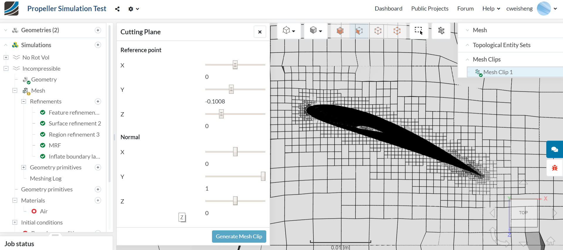
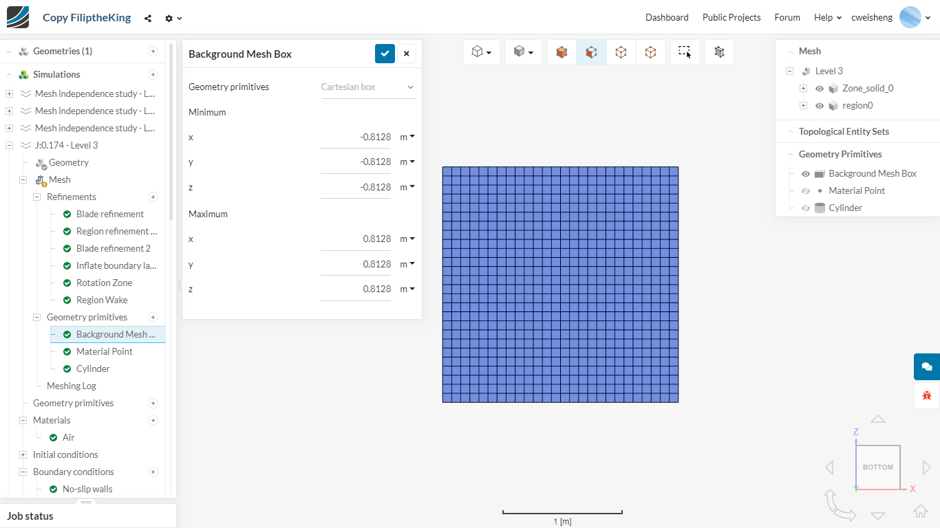
To start, I see this (z direction only for now):

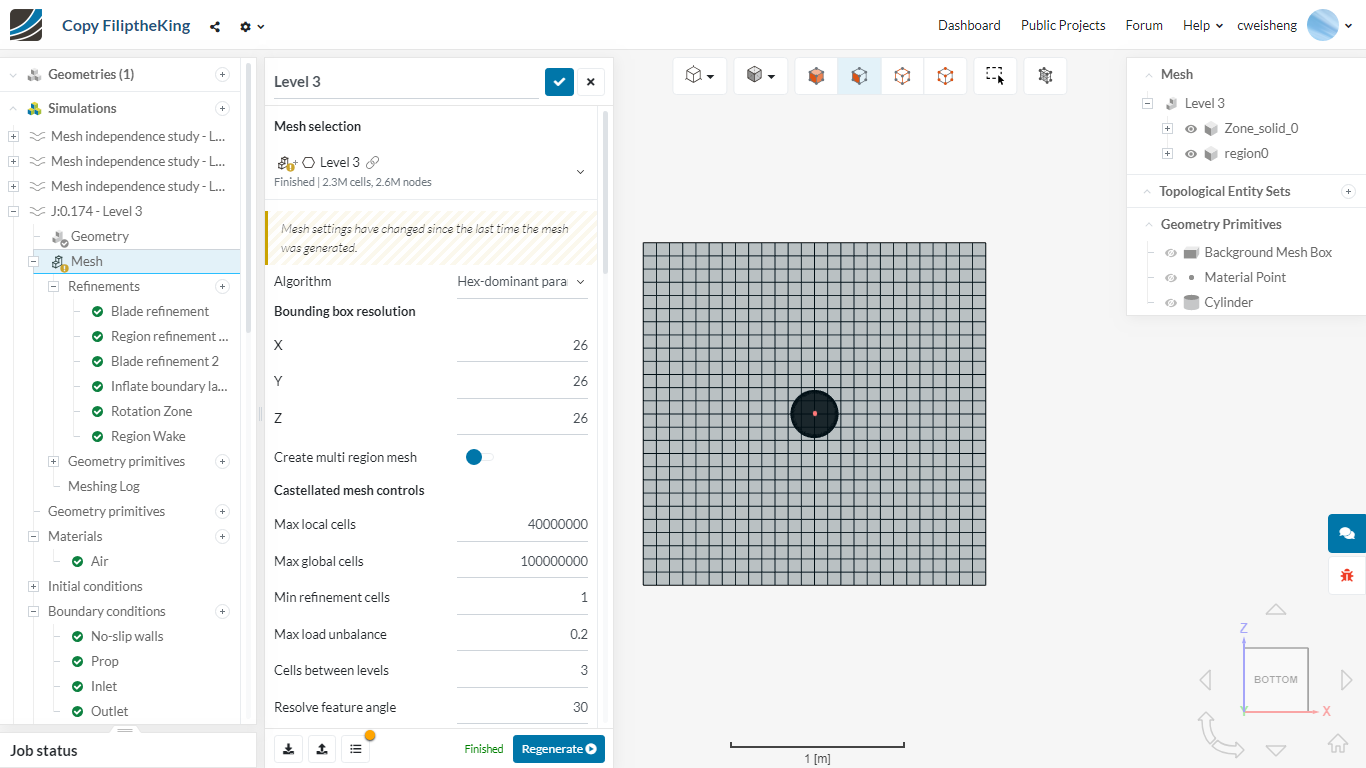
The z range of Background Mesh Box (BMB) is 2.2m. In your meshing parameters you have chosen split your Level 0 z range into 58 faces. That is 2.2/58 = 0.0379 m. By the way, I always make my Level 0 faces 1.28m square on all axis (that makes a very nice level/facesize table). If you really want to start finer, make sure the level 0 face size is some large power of 2, in your case if you want to stay close to what you have, try Level 0 at 0.0512m (you will start to commit levels sizes to memory at that point) .

So here are your z face sizes at various levels:

level z face size (m)
0 0.03790000
1 0.01895000
2 0.00947500
3 0.00473750
4 0.00236875
5 0.00118438
6 0.00059219
7 0.00029609
8 0.00014805
9 0.00007402
10 0.00003701
11 0.00001851
12 0.00000925
13 0.00000463
14 0.00000231

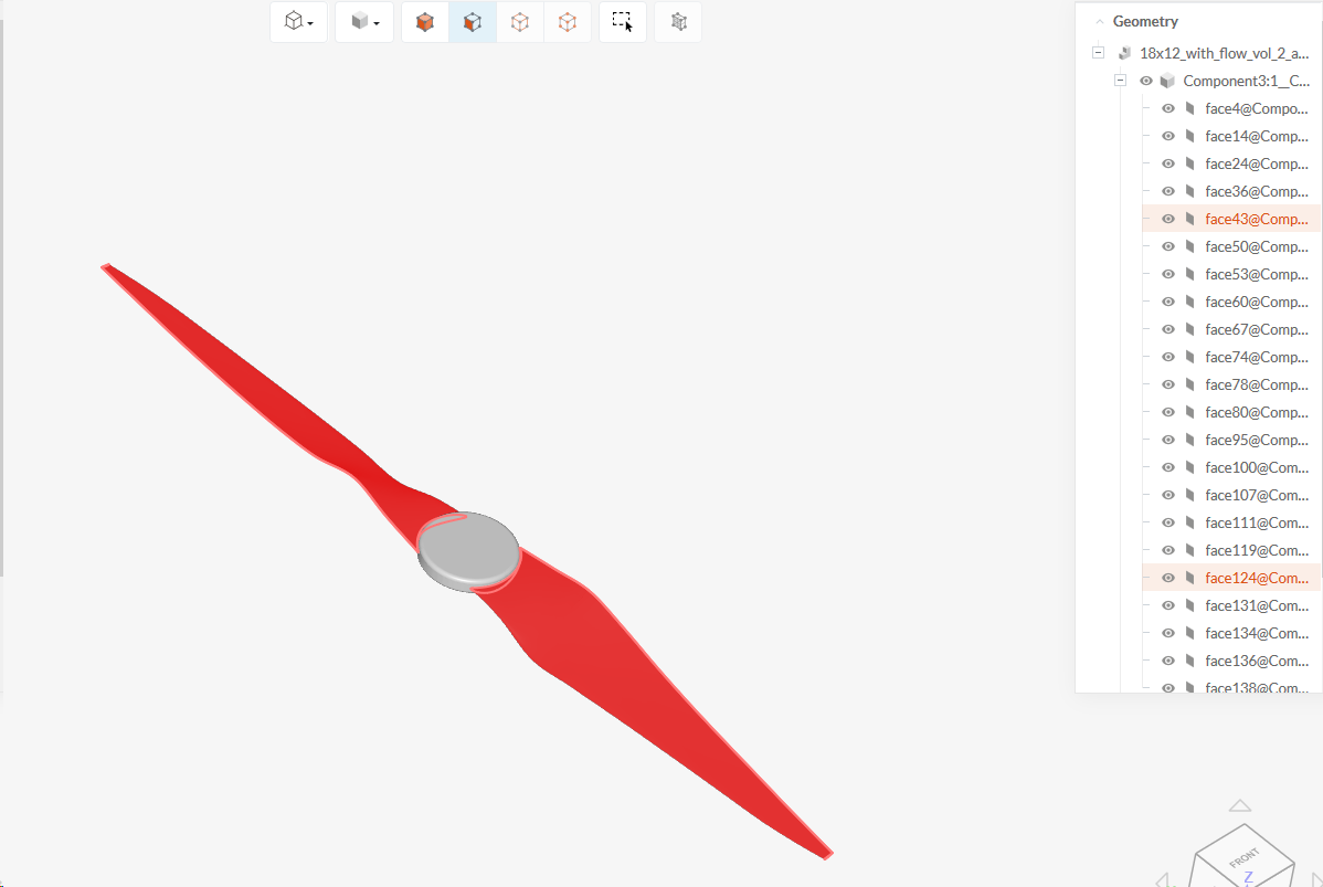
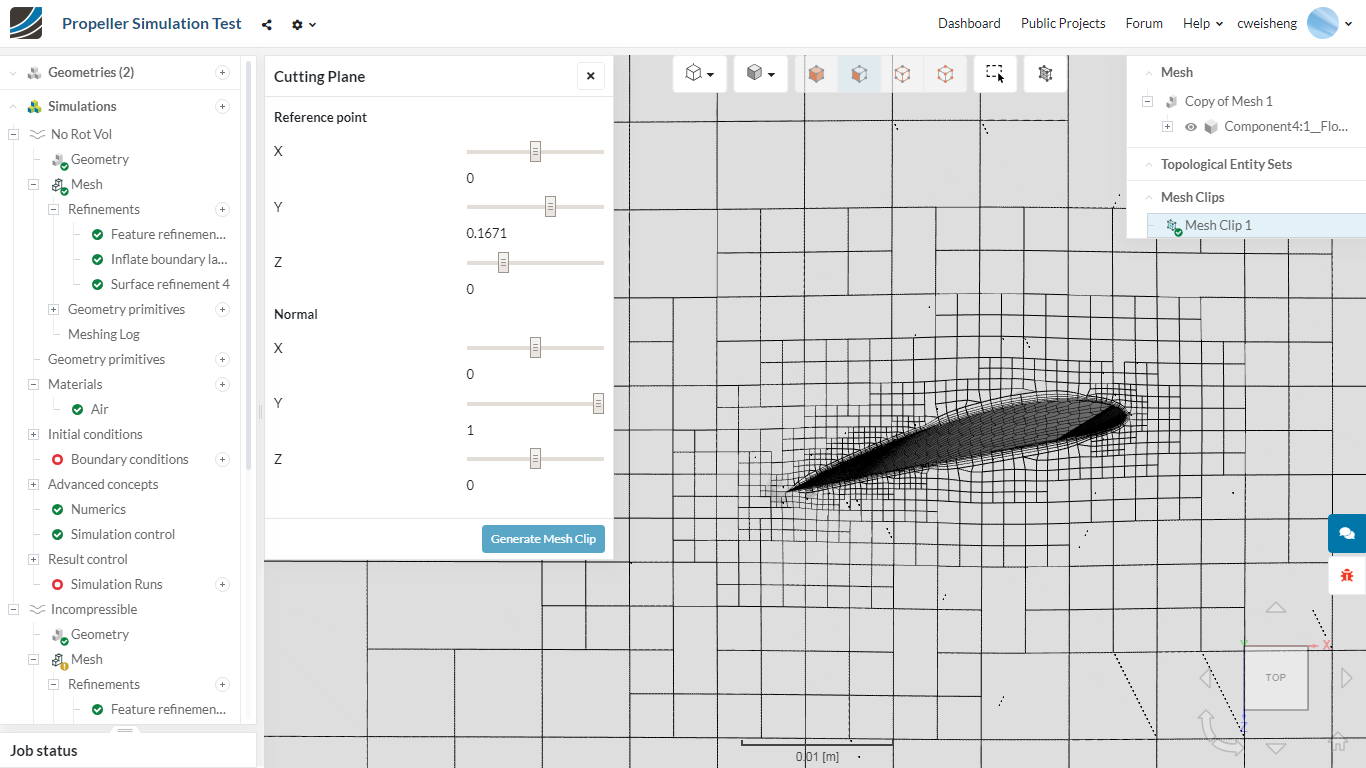
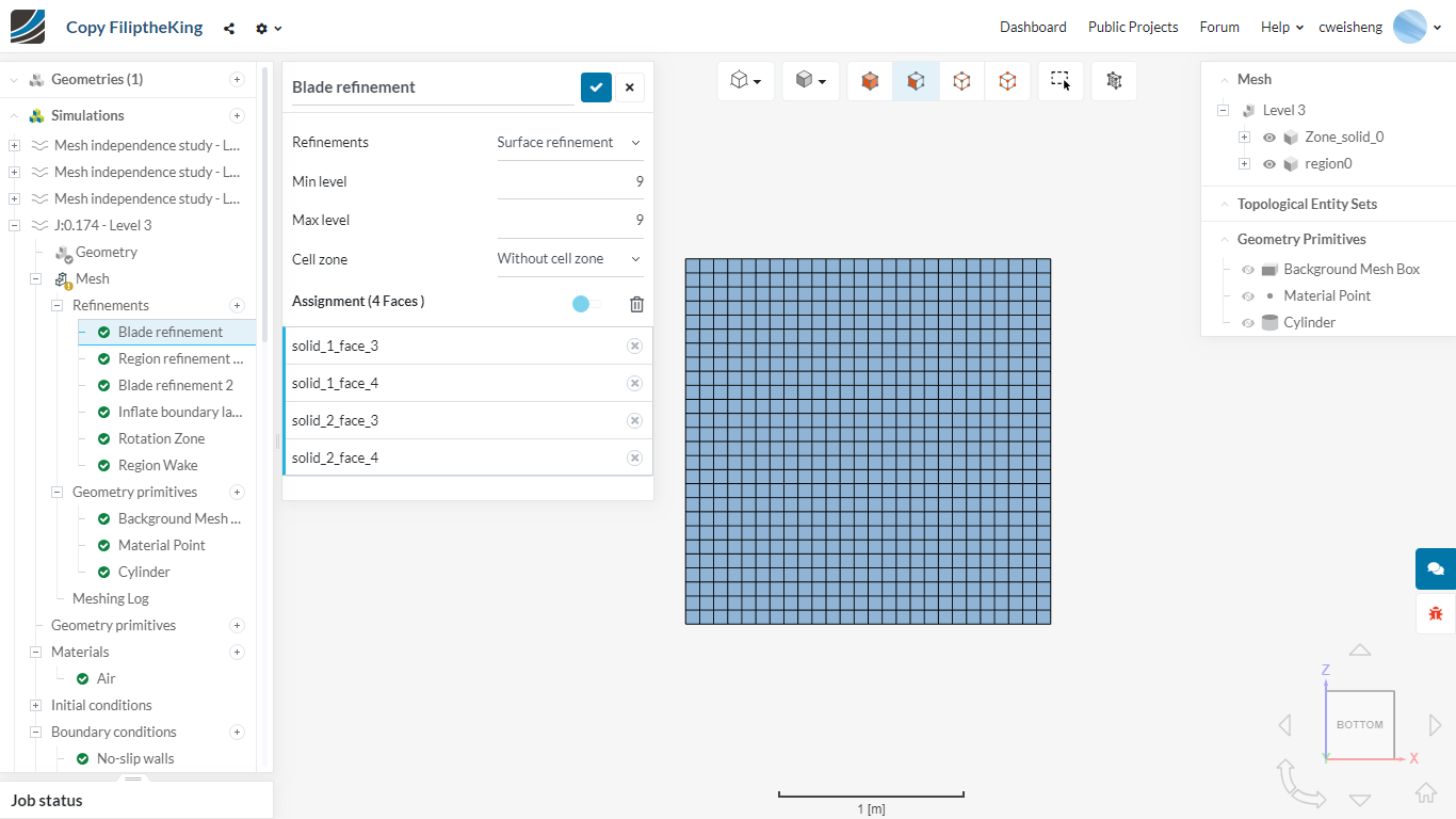
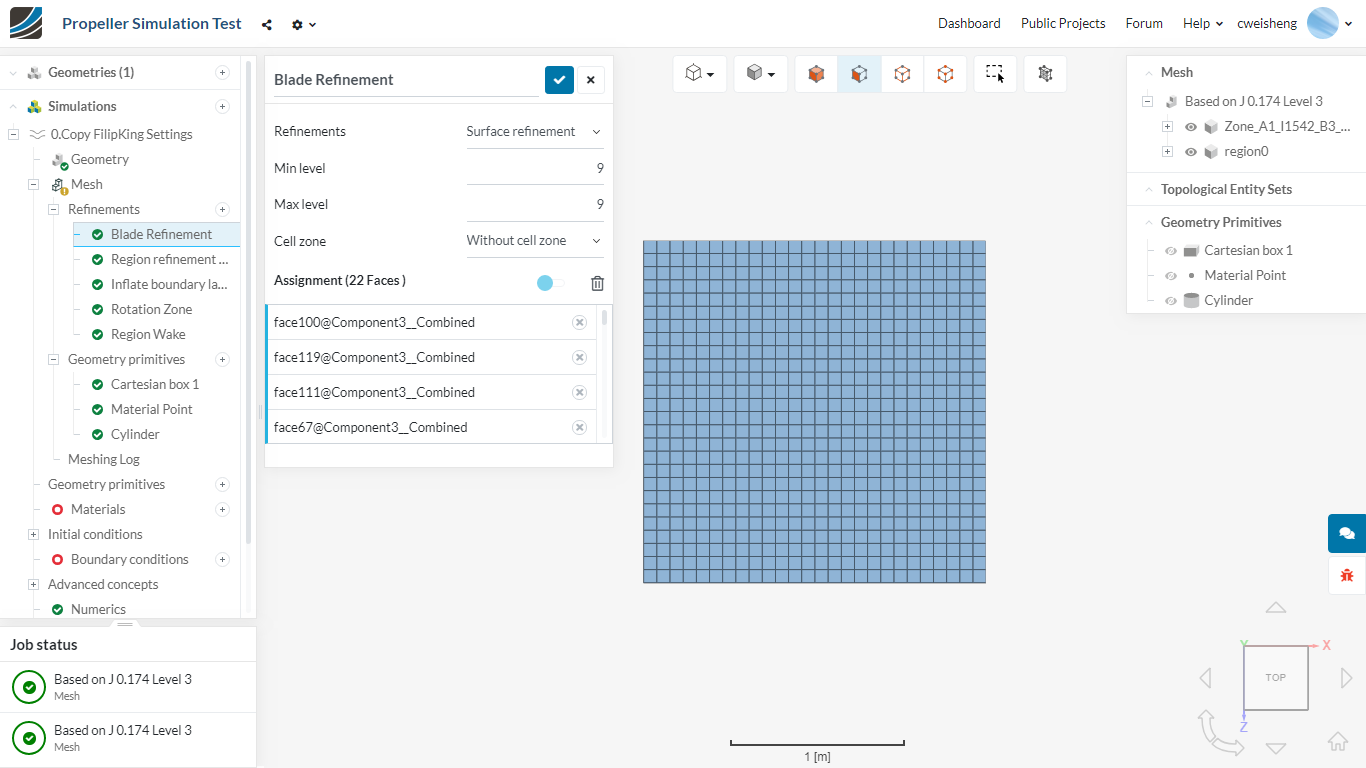
I see that your trailing edge is about 0.00001 m thick at the tip. You have only refined all prop surfaces as level 6 to 7 (0.00002961 m). So you won’t see any trailing edge faces in the mesh.

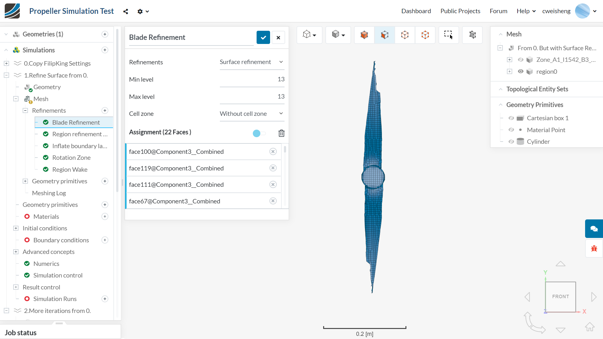
If you want faces on the TE this means you should put a surface refinement of level 12 or 13 on the trailing edge faces if you want to get some cells on the TE.

Similarly, your tip chord is only about 0.005m and you need the prop surface refinement to go from level 6 to 12 (or 13) to get some cells around the LE radius.

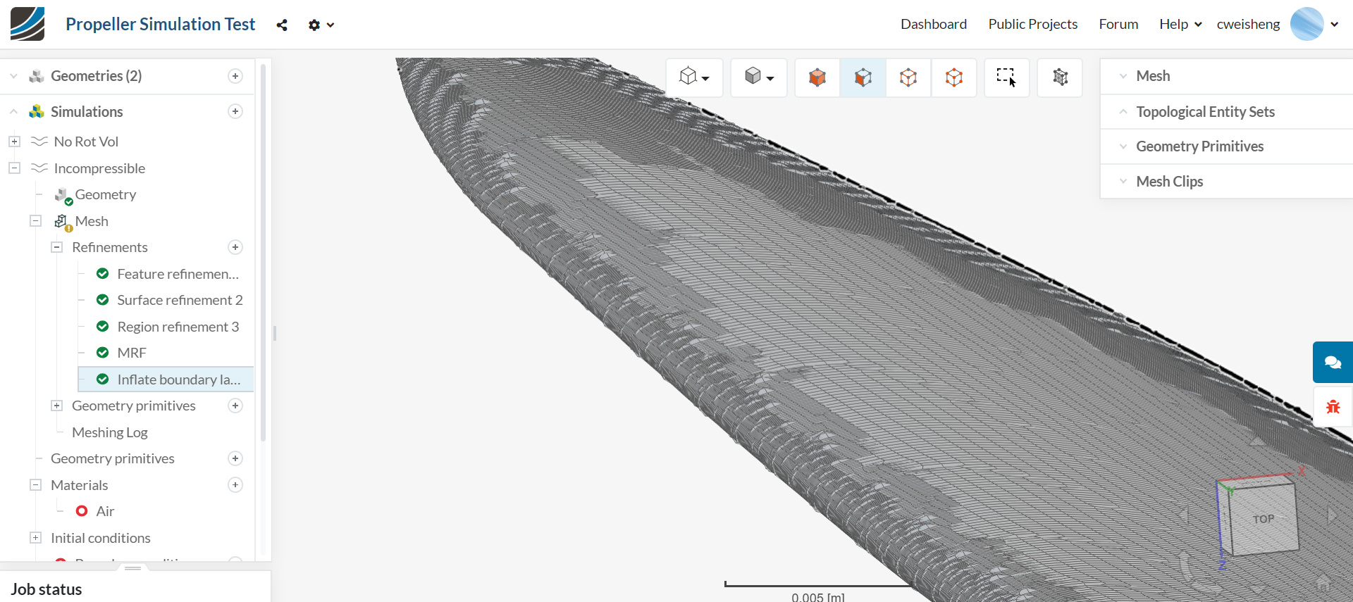
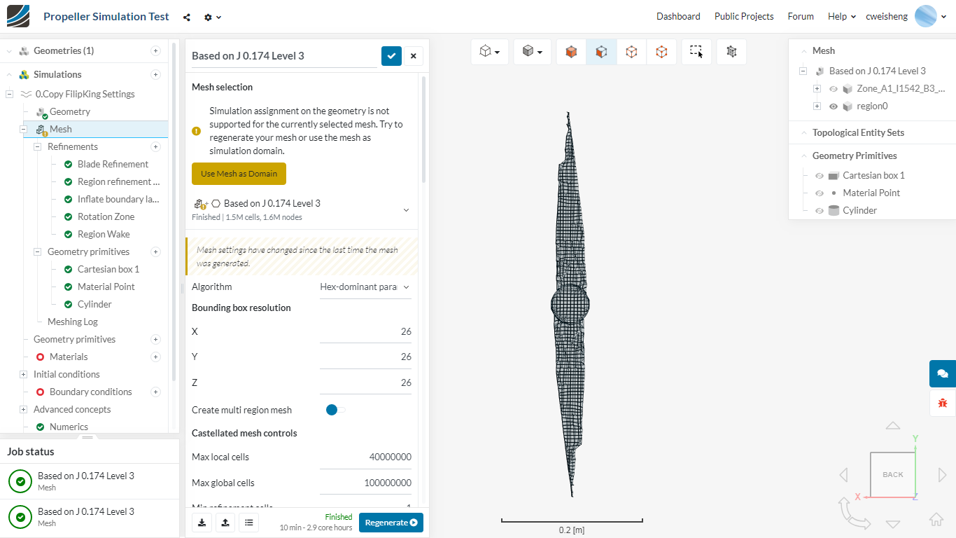
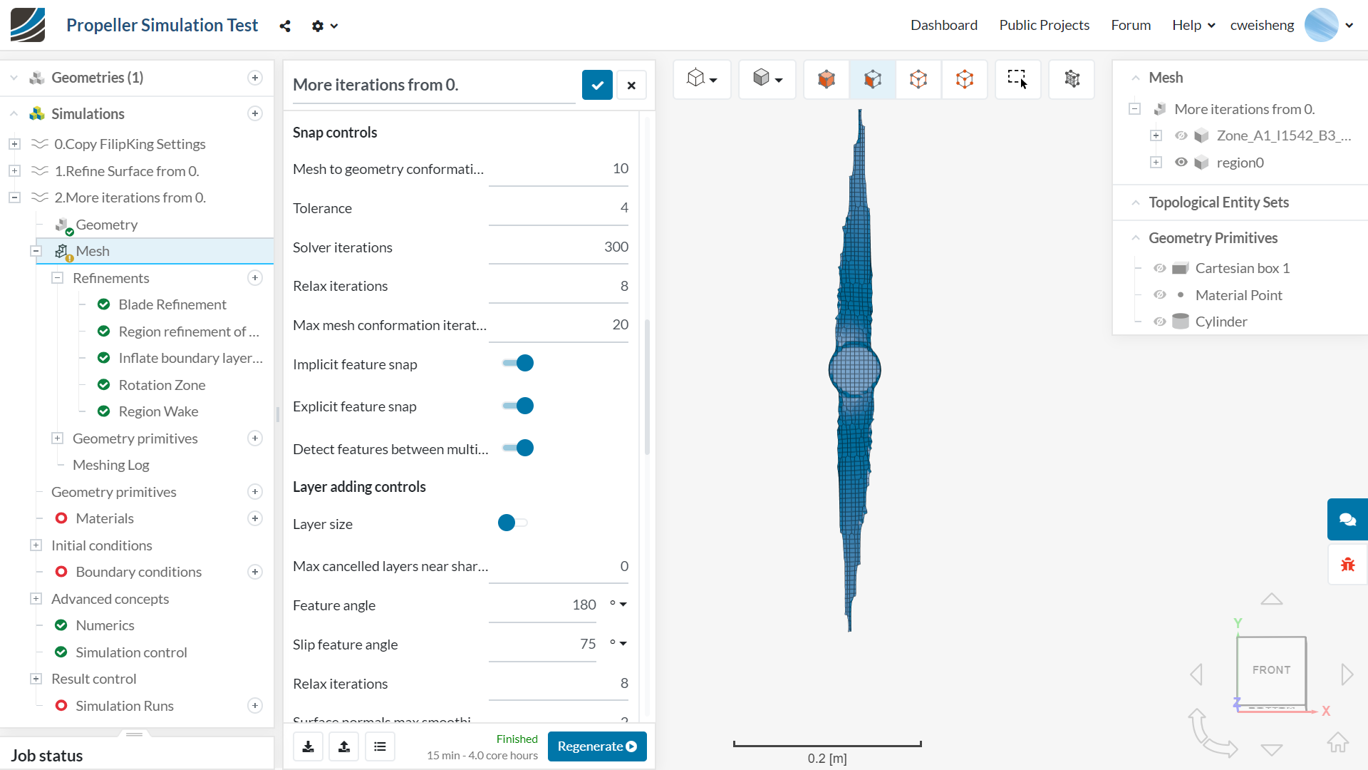
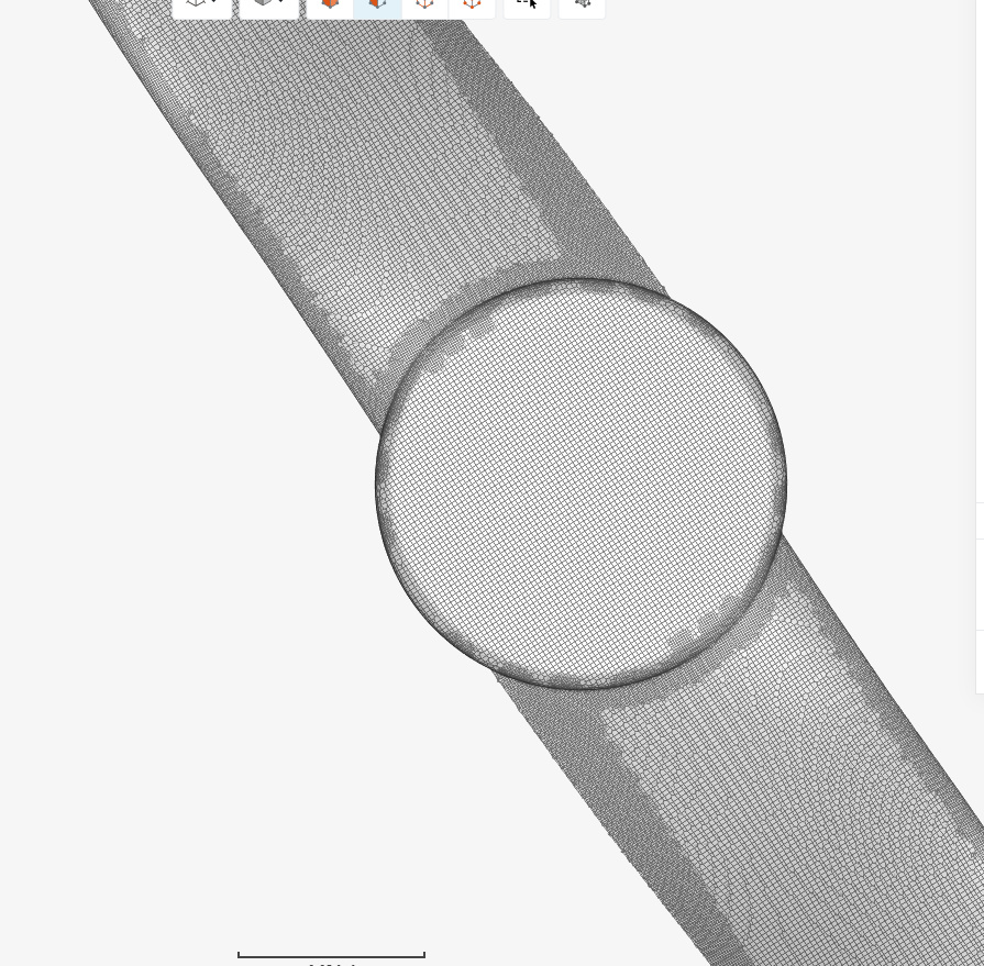
BUT as for the real problem:

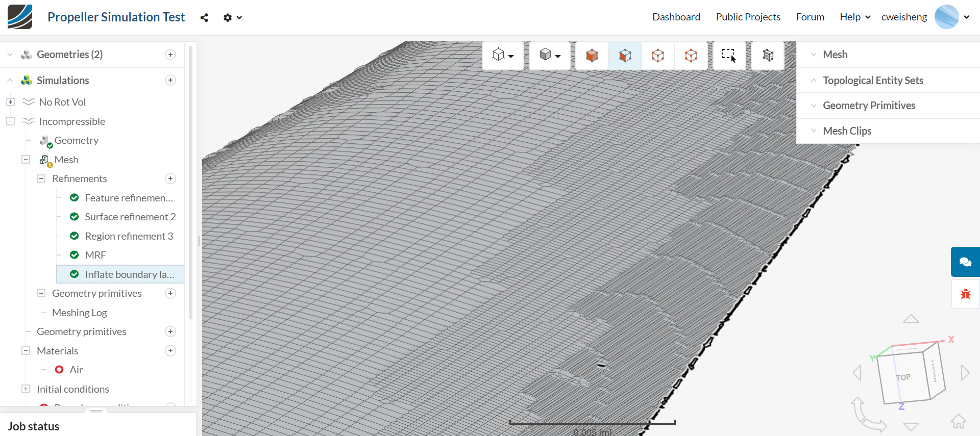
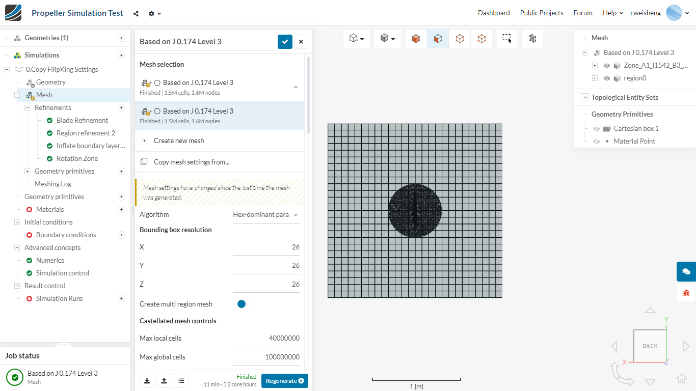
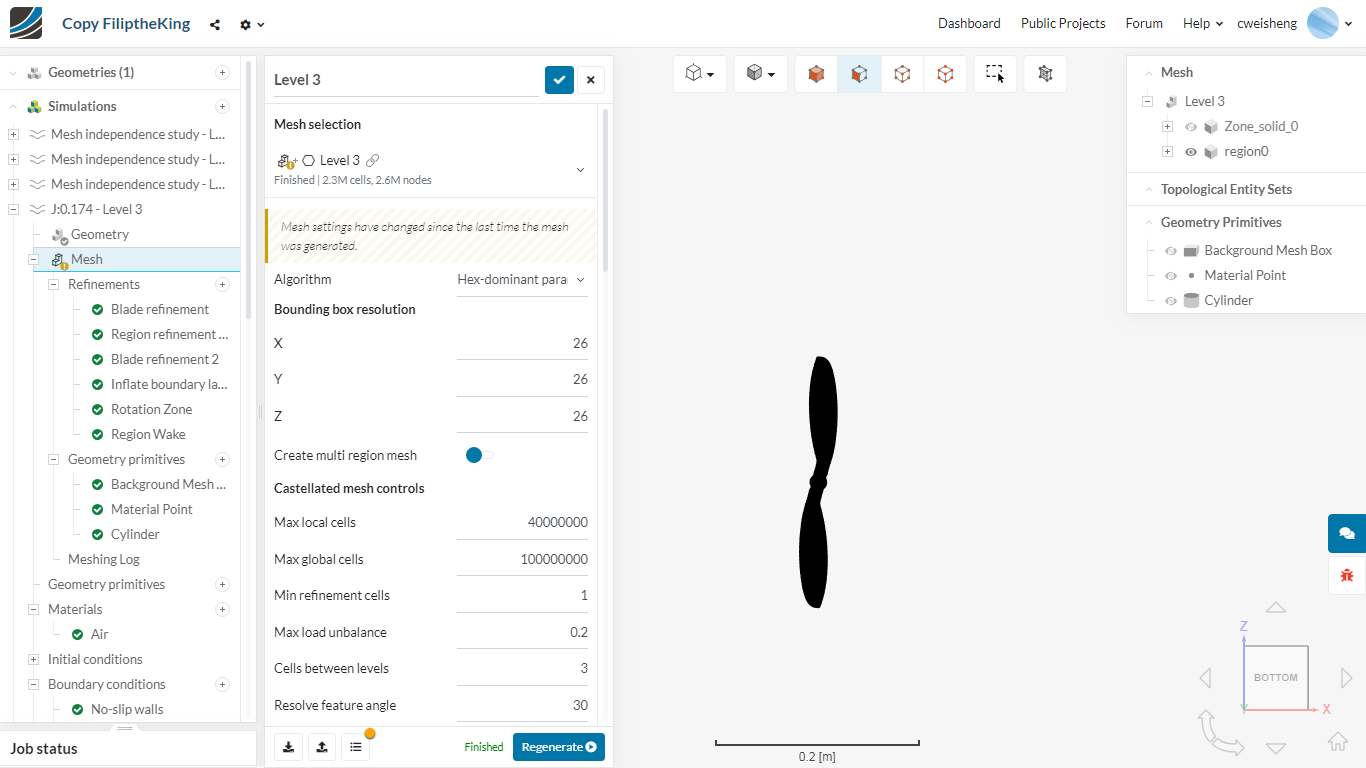
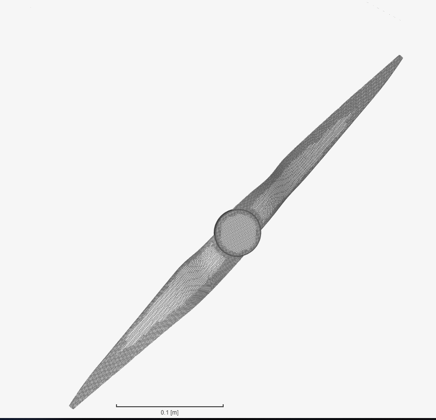
For some reason you are losing your prop geometry completely in the mesh, so, when it is time to layer, there is nothing to layer.

I would try fixing your surface refinements to take into account my above comments and then meshing and layering with just the BMB and the prop to start with. Add the other refinement cylinders later.

Then we will go from there…

Also, I rarely use feature refinements…

Note. Here is a similar project to yours and you might find clues there…

@Filiptheking

Hi, I was pointed to your project and decided to follow exactly what you did. I am not that concerned about the simulation results now but would rather demonstrate (to myself) that I can form the boundary layers. Have done many such validations in STARCCM+ before but unfortunately have had no experience in OpenFOAM.

I used the mesh settings in your project (J:0.174-Level 3 mesh). Although my propeller diameter is larger than yours, if I understand it correctly, the mesh size reference uses that of the Background Mesh Box as Level 0.
This is yours:


This is mine:

Level 0 looks right to me.

I then used the same settings found in your refinements:

  • Blade refinement to Level 9 (I used Level 9 for all surfaces although you have another at Level 8)
  • Region refinement of rotation zone at Level 4
  • Inflate boundary layer (8 layers, 1.4 expansion, 0.00008328) - i am just trying to see if BL can form on my simulation, I know my y+ should be different from yours
  • Rotation Zone surface refinement at Level 4 (Inside Cell Zone)
  • Region Wake refinement at Level 2 (inside)

However, it is immediately clear that something is wrong. My surface mesh is nowhere as small as yours even though we have the same background mesh box size and resolution, and same surface refinement levels.
This is yours:


This is mine:

Can anyone help to explain this? I don’t understand what has gone wrong and have tried many suggestions by other members. I am beginning to wonder if its a matter of my CAD or if somehow my free account has limitations?:sweat_smile:

Some comparisons for proof:
Your Background Mesh Box:


My Background Mesh Box:

Your Blade Refinement:


My Blade Refinement:

I will try to change the settings for a finer mesh but I am on the free plan so I am not sure if the machines have sufficient memory to do that. But I will try.

Hi @cweisheng and thanks for the detailed investigations, quite interesting :slight_smile:

If you have any trouble running the meshing process you can simply tag me here and I will run the mesh for you to see what parameters we have to change in order to get some decent results for some first runs.

Let us know how things go!

Jousef

@jousefm

How do I take up your offer?

My further explorations with meshing parameters did not yield improvements. One more thing I can try (tonight when I can access CAD) is probably to output geometry as a fine-res STL file? Currently I have tried both .iges and .step:

Hi @cweisheng!

You can share the project with me and I will give it a spin later on - letting you know what you could adapt.

Best,

Jousef

@jousefm

Hi, thanks, have shared it with you although it was public before already. Thanks in advance!

My free Autodesk Fusion 360 has no option to output as STL so I tried some other formats like SMT, SAT… didn’t work.

I tried IGES again - didn’t work (when I adopted @Filiptheking 's settings, I also used STEP like he did)

I tried with IGES but for the Surface Refinement selection, rather than selecting “faces”, I selected the whole Propeller “solid” - didn’t work.

Not much point to show graphics here because they are the same as before - where the surface mesh of the propeller is not even well formed.

Hi @cweisheng

I will take a look at your project today and will come back with a suitable solution as soon as possible.

Thanks
Ani

1 Like

Hi @cweisheng
I just copied your project and meshed the geometry using just the surface refinement on the blade surface with the extreme value of refinement as 3 to 4 and this was the result-

I think that you should try preparing the mesh from the scratch and instead of just blindly following the values used in the tutorial you should spend more time playing with different mesh features and refinement level to have a better understanding of what role each parameter plays. This will also prepare you in deciding the regions where you should add more cells and ignore the other regions. Refinement level of 9 and that too in your 1st simulation is totally unnecessary, as you should try to simulate first with a coarse mesh and then perform a mesh independence study which will give you a feel that now your current mesh level is sufficient for this problem and there is no need in further increasing the mesh quality.

By the way I also made another mesh with surface refinement on the blade surface with the extreme value of refinement as 4 to 5 and this was the result-

If you have any kind of doubt, I am always there to help you. :slightly_smiling_face:

Thanks
Ani

2 Likes